
74HC595 Shift Register with Arduino
Published
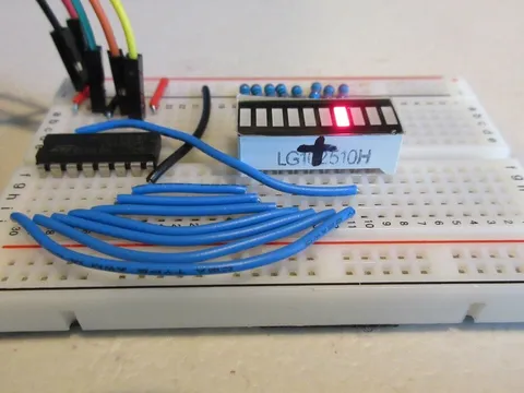
Controlling LEDs from the 74HC595 shift register
What is a Shift Register?
A shift register loads the data on its inputs and then shifts it to its output once every clock cycle.
A shift register essentially consists of several single-bit D-Type Data Latches, one for each data bit, either a logic 0 or 1, connected together in a serial-type daisy-chain arrangement so that the output from one data latch becomes the input of the next latch.
Data bits may be fed in or out of a shift register in a serial manner, or all together at the same time in a parallel configuration.
The number of individual data latches required to make up a single shift register is usually determined by the number of bits to be stored, with the most common being 8 bits wide made from eight data latches.
Shift registers are used for the storage or movement of data. They are commonly used inside electronics to store data to convert between serial and parallel. The individual data latches that make up a single shift register are all driven by a common clock signal, making them synchronous devices.
Shift registers usually have a clear or reset connection so that they can be set or reset as needed.
What is the 74HC595?
The datasheet refers to the 74HC595 as an "8-bit serial-in, serial or parallel-out shift register with output latches; 3-state."
— Arduino website
Serial to Parallel Shifting-Out with a 74HC595
Serial to Parallel Shifting-Out with a 74HC595
"8-bit serial-in" means that the register is 8-bit (8 flip-flops in the chip). It also only supports a serial input (one data and one clock line to transmit data)
"serial or parallel-out" can be broken down into two parts: Serial-in Parallel-out and Serial-in Serial-out.
Serial-in Parallel-out (SIPO) means the shift register receives data via two pins: data and clock. Its output is parallel: each of the eight outputs represents one bit in the received data.
Serial-in Serial-out (SISO) means that the register has data shifting in and out of it serially, as explained above. The serial data shifting out can be used for daisy-chaining two registers. This means that you can control over one register while maintaining the constant pin usage of 3 pins (not explained on this page).
"3-state" means that an output can have the usual "high" and "low" states, as well as a "high-impedance" state (it is electrically disconnected from the rest of the circuit). This third state is achieved by setting the output enable pin (13) high.
74HC595 Pinout
| Pin | Pin name | Function |
|---|---|---|
1 | Q1 | Parallel data output 1 |
2 | Q2 | Parallel data output 2 |
3 | Q3 | Parallel data output 3 |
4 | Q4 | Parallel data output 4 |
5 | Q5 | Parallel data output 5 |
6 | Q6 | Parallel data output 6 |
7 | Q7 | Parallel data output 7 |
8 | GND | Ground |
9 | Q7' | Serial data output |
10 | MR | Master reset (active low) |
11 | SH_CP | Shift register clock |
12 | ST_CP | Storage register clock |
13 | OE | Output enable (active low) |
14 | DS | Serial data input |
15 | Q0 | Parallel data output 0 |
16 | VCC | Supply voltage |
Hardware Overview
Below is a summary of the 74HC595 and its working principles:
Before sending data to the chip, the latch pin needs to be pulled low. This is telling the register to not yet update the outputs. It will do so when latch is high again so the outputs don’t update and flicker when the data is being fed in.
The shift register has eight memory spaces, each of which can hold one bit. To set each as 1 or 0, we feed in the data using the Data and Clock pins of the chip. As a clock pulse enters the register, it means that there is a new bit to read. These are the red lines in the diagram above: the data and clock pulses need to line up so the shift register can properly count them.
The output states (in the green box) that are set high only change state when the latch pin is pulled high (indicated by another red line). This means that after all data has finished transferring, the latch pin needs to be set high to let the outputs update.
Software Overview
The 74HC595 can be controlled with the Arduino built-in function shiftOut, whose syntax is below:
shiftOut(dataPin, clockPin, bitOrder, value);dataPin: Arduino pin connected to the shift register’s data pinclockPin: Arduino pin connected to the shift register’s clock pinbitOrder: Order to shift the bits out. The constantsLSBFIRSTandMSBFIRSTshift the bits out with the least significant bit (LSB) and most significant bit (MSB) first, respectively.value: Data shifted out. This should be abyteoruint8_t, not exceeding 255.
For example, to send the byte of data B10010101 LSB first to a shift register with the clock pin connected to Arduino pin 6 and data pin connected to Arduino pin 4, you would use:
shiftOut(4, 6, LSBFIRST, B10010101);Combining this with the latch pin, assuming it is connected to Arduino pin 5, you would use:
digitalWrite(5, LOW);
shiftOut(4, 6, LSBFIRST, B10010101);
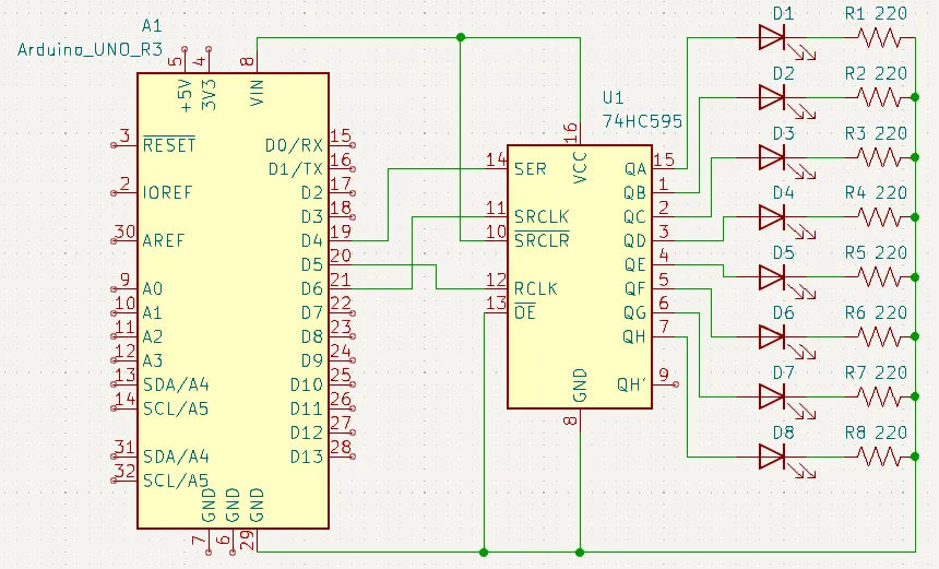
digitalWrite(5, HIGH);Schematic
Example
// Define constants for pins
#define LATCH 5
#define CLOCK 6
#define DATA  4

byte out = 0;
int del = 70; // Delay time between segments

void setup() {
  // Configure all pins as outputs
  pinMode(LATCH, OUTPUT);
  pinMode(CLOCK, OUTPUT);
  pinMode(DATA, OUTPUT);
}

void loop() {
  // Incremented for loop
  for (int i = 0; i < 8; i++) {
    // Clear the output, then set one bit
    out = 0;
    bitSet(out, i);

    // Send to shift register
    sendData(out);
    delay(del); // Delay
  }

  // Decremented for loop
  for (int i = 7; i > -1; i--) {
    // Clear the output, then set one bit
    out = 0;
    bitSet(out, i);

    // Send to shift register
    sendData(out);
    delay(del); // Delay
  }
}

void sendData(byte out) {
  // Send data to shift register
  digitalWrite(LATCH, LOW);
  shiftOut(DATA, CLOCK, LSBFIRST, out);
  digitalWrite(LATCH, HIGH);
}Program Flow
At the start of the program, we declare the pins used to transmit data, then set them as outputs in setup.
In loop, there are two for loops - one incrementing and one decrementing. These will make the LEDs scan back and forth.
Setting Bits and Sending Data
In the body of each loop, the out variable will be pushed out to the register. We set it to 0 (clearing all bits), then turn a single bit to 1 with bitSet. The bit number is the LED we want to turn on.
After setting the bit, we use sendData to send the byte to the register and briefly wait so the LEDs don’t change too quickly.
In the sendData function, you will see that it uses the shiftOut function in the same way explained above.