/*
   CycleDigits.ino
   This sketch displays the digits 0-9 on all segments. After each iteration,
   the decimal point is toggled.
   Created on 8 April 2020 by Aidan Sun
*/

#include <SevenSegmentShield.h>
#include <Wire.h>

Display ds;
bool isDpOn = false; // Decimal point off at start

void setup() {
  Wire.begin();
  ds.begin();
}

void loop() {
  // Outer loop to cycle through all numbers
  for (int i = 0; i < 10; i++) {
    // Inner loop to cycle through all 4 digits
    for (int j = 1; j < 5; j++) ds.writeDigit(j, i, isDpOn); // Digit, value, decimal point

    delay(1000); // 1 second delay between values
  }

  ds.clear(); // Clear display
  delay(1000);

  isDpOn = !isDpOn; // Toggle decimal point
}Seven-Segment Shield
Published
Using the Seven-Segment Shield's display, EEPROM, temperature sensor, and RGB LED with Arduino
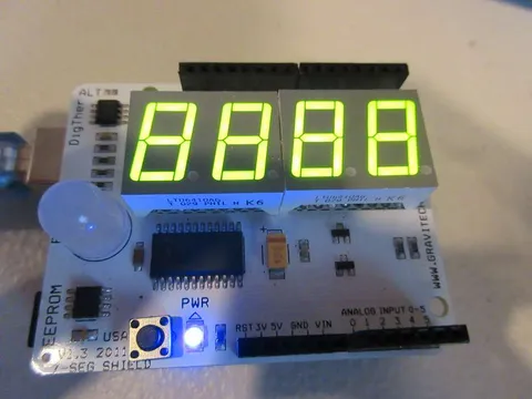
The Seven-Segment Shield
The shield is available here. It has the following onboard devices:
Four bright green 7-segment digits
I2C 7-segment driver (NXP SAA1064)
128K I2C EEPROM (24LC128)
I2C Digital thermometer (TMP75)
10mm RGB LED (with PWM)
Note | The shield uses Arduino pins D3, D5, D6 (for the LED), A4, and A5 (for I2C), so they cannot be used for anything else. |
Library
This project uses my SevenSegmentShield library. Download the library in Zip format
All example code is under .
Displaying Digits and Letters
The example displays the digits 0-9 on each segment.
The example directly writes to the segments, displaying "-AbC".
/*
   DisplayChars.ino
   This sketch displays characters such as letters and dashes on the segments.
   Created on 9 April 2020 by Aidan Sun
*/

#include <SevenSegmentShield.h>
#include <Wire.h>

Display ds;

void setup() {
  Wire.begin();
  ds.begin(); // Initialize display
}

void loop() {
  // Display a dash on segment 1
  ds.writeDigitData(4, 64); // digit number, data to write

  // Display the letters A-C on segments 2-4
  ds.writeDigitData(3, 119); // A
  ds.writeDigitData(2, 124); // B
  ds.writeDigitData(1, 57);  // C
}
Initializing the Display
Wire.begin must be called before using any of the shield’s I2C devices to initialize the communication bus.
The begin method of the Display class sets the default brightness for the LEDs. (See "Cycling Brightness")
Displaying on a Single Digit
Both methods below take the following parameter:
digit: The digit to write to, from 1 (rightmost on the shield) to 4 (leftmost)
writeDigit: Displays a digit. Takes the following parameters:
digitvalue: The numeric value to show on the digit (0-9)decimalPoint: If the digit’s decimal point is shown (trueto show,falseto hide)
writeDigitData: Controls the individual segments on a digit.
digitvalue: 1-byte integer containing the segments to display
Segment Values
Segment values may be added together to display them together:

Clearing the Display
clear: Turns off all segments on the display. Takes no parameters.
Displaying Integers
Integers can also be displayed on the shield. An example is at .
/*
   DisplayNum.ino
   This sketch displays numbers on the shield with displayInt().
   Created on 9 April 2020 by Aidan Sun
*/

#include <SevenSegmentShield.h>
#include <Wire.h>

Display ds;

void setup() {
  Wire.begin();
  ds.begin();
}

void loop() {
  int number = random(-999, 10000); // Generate a random number from -999 to 9999
  ds.displayInt(number); // Display the number
  delay(1000); // Wait to let the user see the number
}
The code above randomly generates integers and displays them with the function below:
displayInt: Shows an integer on the entire display.
number: Number to show (-999 to 9999)
Cycling Brightness
The brightness of the display can be adjusted by changing the amount of current the LEDs receive. An example is at .
/*
   CycleBrightness.ino
   This sketch cycles through the brightness for the segments.
   The possible values are 3mA, 6mA, 9mA, 12mA, 18mA, and 21mA.
   Created on 8 April 2020 by Aidan Sun
*/

#include <SevenSegmentShield.h>
#include <Wire.h>

Display ds;

void setup() {
  Wire.begin();
  ds.begin();
  ds.displayInt(8888); // Display the number 8888
}

void loop() {
  uint8_t brightnessLevels[] = { BRIGHTNESS_3MA, BRIGHTNESS_6MA, BRIGHTNESS_9MA, BRIGHTNESS_12MA, BRIGHTNESS_18MA, BRIGHTNESS_21MA };

  for (int i = 0; i < 6; i++) {
    ds.writeBrightness(brightnessLevels[i]);
    delay(500); // 1/2 second delay
  }
}
The code loops through each possible current value, passing each to the function:
writeBrightness: Sets the brightness of the seven-segment display. The default current is 12 mA.
brightness: Current value to determine brightness. Possible values are:BRIGHTNESS_3MA (3 mA current)
BRIGHTNESS_6MA (6 mA current)
BRIGHTNESS_9MA (9 mA current)
BRIGHTNESS_12MA (12 mA current)
BRIGHTNESS_18MA (18 mA current)
BRIGHTNESS_21MA (21 mA current)
Using the EEPROM Chip
The 24LC128 chip on the shield can hold 128 kB of data. The example demonstrates performing I/O on the addresses of the EEPROM.
/*
   ReadWrite.ino
   This sketch reads and writes to the 24LC128 on the shield.
   Created on 10 April 2020 by Aidan Sun
*/

#include <SevenSegmentShield.h>
#include <Wire.h>

MemoryChip mc;

void setup() {
  Wire.begin();
  Serial.begin(9600);

  // Write to the first 20 bytes
  for (int i = 0; i < 20; i++) {
    mc.writeByte(i, i); // address, data
    delay(5); // Short delay to prevent losing communication data
  }

  // Read from the first 20 bytes
  for (int i = 0; i < 20; i++) {
    uint8_t value = mc.readByte(i); // Read from the address

    // Print the data in the byte
    Serial.print("EEPROM address ");
    Serial.print(i);
    Serial.print(" holds ");
    Serial.println(value);
  }
}

void loop() {}
Serial monitor output
EEPROM address 0 holds 0
EEPROM address 1 holds 1
EEPROM address 2 holds 2
EEPROM address 3 holds 3
EEPROM address 4 holds 4
EEPROM address 5 holds 5
EEPROM address 6 holds 6
EEPROM address 7 holds 7
EEPROM address 8 holds 8
EEPROM address 9 holds 9
EEPROM address 10 holds 10
EEPROM address 11 holds 11
EEPROM address 12 holds 12
EEPROM address 13 holds 13
EEPROM address 14 holds 14
EEPROM address 15 holds 15
EEPROM address 16 holds 16
EEPROM address 17 holds 17
EEPROM address 18 holds 18
EEPROM address 19 holds 19
Reading and Writing Memory
The methods below are part of the MemoryChip class, which represents the onboard 24LC128. They share the following parameter:
address: The address to read or write from
readByte: Returns the byte at the specified memory address.
address
writeByte: Writes the given byte to the specified memory address.
addressdata: Byte to write
Important | After writing to the EEPROM, insert a short delay (such as 5 ms in the example) to prevent the loss of communication data. |
Controlling the LED
The shield’s RGB LED is connected to three PWM pins on the Arduino. The example uses PWM to display different colors.
/*
   CycleColors.ino
   This sketch cycles through 48 colors on the LED.
   Created on 10 April 2020 by Aidan Sun
*/

#include <SevenSegmentShield.h>

RgbLed led;

const long COLORS[48] = {
  0xFF2000, 0xFF4000, 0xFF6000, 0xFF8000, 0xFFA000, 0xFFC000, 0xFFE000, 0xFFFF00,
  0xE0FF00, 0xC0FF00, 0xA0FF00, 0x80FF00, 0x60FF00, 0x40FF00, 0x20FF00, 0x00FF00,
  0x00FF20, 0x00FF40, 0x00FF60, 0x00FF80, 0x00FFA0, 0x00FFC0, 0x00FFE0, 0x00FFFF,
  0x00E0FF, 0x00C0FF, 0x00A0FF, 0x0080FF, 0x0060FF, 0x0040FF, 0x0020FF, 0x0000FF,
  0x2000FF, 0x4000FF, 0x6000FF, 0x8000FF, 0xA000FF, 0xC000FF, 0xE000FF, 0xFF00FF,
  0xFF00E0, 0xFF00C0, 0xFF00A0, 0xFF0080, 0xFF0060, 0xFF0040, 0xFF0020, 0xFF0000
};

const int NUM_OF_COLORS = 48;

void setup() {}

void loop() {
  for (int i = 0; i < NUM_OF_COLORS; i++) {
    long currentColor = COLORS[i];
    led.displayHexColor(currentColor); // Display the color
    delay(100);
  }

  // Turn off the LED
  led.turnOff();
  delay(1000);
}
Hex and RGB Colors
The example above defines 48 hex colors. Each color is an integer with 8 bits of red (leftmost bits), green, and blue (rightmost bits) values.
displayHexColor: Displays a color on the LED given in hexadecimal format.
hh: Color
displayRGBColor: Displays a color on the LED given with individual red, green, and blue components.
r: 8-bit red valueg: 8-bit green valueb: 8-bit blue value
turnOff: Turns the LED off. Takes no parameters.
Reading from the TMP75
The example uses the shield to create a thermometer. The temperature is displayed on the segments, and the LED changes color accordingly.
/*
   Thermometer.ino
   This sketch reads the temperature from the TMP75 and displays it on the segments.
   It will also change the color of the LED based on the temperature.
   Created on 10 April 2020 by Aidan Sun
*/

#include <SevenSegmentShield.h>
#include <Wire.h>

Display ds;
RgbLed led;
TMP75 tmp;

void setup() {
  Wire.begin();
  ds.begin();
  tmp.begin();
  Serial.begin(9600);
}

void loop() {
  // Get the temperature
  float temp = tmp.read();

  // Display the temperature
  ds.displayInt(round(temp));
  Serial.print("Temperature: ");
  Serial.println(temp);

  // Change the color of the LED based on the temperature
  if (temp <= 25) led.displayRGBColor(0, 0, 255); // Cold, LED will be blue
  else if (temp > 25 && temp <= 30) led.displayRGBColor(255, 127, 0); // Warm, LED will be yellow
  else led.displayRGBColor(255, 0, 0); // Hot, LED will be red

  delay(500); // Delay at end of loop
}| Cold | Warm | Hot |
|---|---|---|
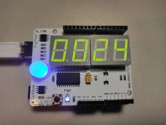 | 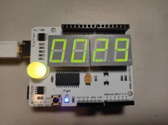 | 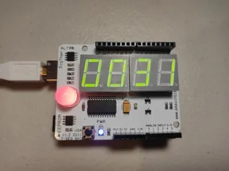 |
Serial monitor output
Temperature: 27.69
Temperature: 27.94
Temperature: 28.37
Temperature: 28.75
Temperature: 29.12
Temperature: 29.31
Temperature: 29.50
Temperature: 29.62
Temperature: 29.81
Temperature: 29.87
Temperature: 29.94
Temperature: 30.06
Temperature: 30.00
Temperature: 29.62
Temperature: 29.44
Temperature: 29.25
Temperature: 29.12
Temperature: 28.94
Temperature: 28.81
All TMP75 functions are contained inside a class called TMP75.
Initializing the TMP75
begin: Initializes the TMP75 and configures it to 12-bit resolution.
Reading the Temperature
read: Returns the temperature read by the TMP75 in degrees Celsius.