LCD Keypad Shield
Published
Using the LCD Keypad Shield's display, backlight, and buttons with Arduino
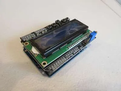
The LCD Keypad Shield
The LCD Keypad shield contains a 1602 LCD connected to pins 4-9 and backlight connected to digital 10. It also has 6 buttons, 5 of which are connected to A0. The sixth is a reset button.
Arduino Pin Connections
LCD RS pin is connected to D8
LCD EN pin is connected to D9
LCD D4 pin is connected to D4
LCD D5 pin is connected to D5
LCD D6 pin is connected to D6
LCD D7 pin is connected to D7
LCD backlight is connected to D10
Buttons are connected to A0
Printing Text
#include <LiquidCrystal.h> // Include library

// Define pin constants
#define RS 8
#define EN 9
#define D4 4
#define D5 5
#define D6 6
#define D7 7

// Create LiquidCrystal object
LiquidCrystal lcd(RS, EN, D4, D5, D6, D7);

void setup() {
  lcd.begin(16, 2); // 16 columns, 2 rows

  lcd.setCursor(0, 0); // Set cursor to row 1, column 1
  lcd.print("Hello, world!"); // Print "Hello, World!"
}

void loop() {}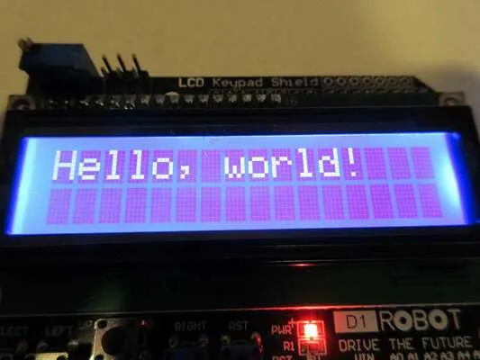
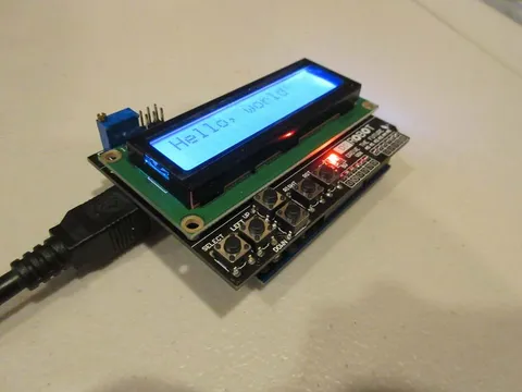
After running the code, it may seem like nothing is displayed. This is because of the contrast adjustment trimpot, which is blue with a gold screw and located in the top left corner of the shield.
To adjust this trimpot, get a flat screwdriver and rotate the screw. Note that this is a precision trimpot, so it can take a few turns to reach the proper value.
Once properly adjusted, you should see the words "Hello, world!" displayed on the screen.
Controlling the Backlight
The LCD’s backlight is connected to digital pin 10. It can be controlled like a normal LED with pinMode and digitalWrite.
#include <LiquidCrystal.h> // Include library

// Define pin constants
#define RS 8
#define EN 9
#define D4 4
#define D5 5
#define D6 6
#define D7 7

#define BKLIGHT 10 // Backlight pin

// Create LiquidCrystal object
LiquidCrystal lcd(RS, EN, D4, D5, D6, D7);

void setup() {
  pinMode(BKLIGHT, OUTPUT); // Set D10 to output

  lcd.begin(16, 2); // 16 columns, 2 rows

  lcd.setCursor(0, 0); // Set cursor to row 1, column 1
  lcd.print("Hello, world!"); // Print "Hello, World!"
}

void loop() {
  // Toggle the backlight every 5 seconds
  digitalWrite(BKLIGHT, HIGH);
  delay(5000);
  digitalWrite(BKLIGHT, LOW);
  delay(5000);
}Controlling the backlight has many useful applications. For example, the backlight could turn off if there is no user interaction for a long time to implement a power-save mode, similar to a cell phone.
Using the Buttons
The shield contains six buttons, five of which are connected to A0. Each switch is connected to a resistor with a unique value. This is a resistor ladder, and it saves pins by connecting multiple buttons to one analog input.
When pressed, each button generates a different value on the A0 pin. This is how we can know when a button is pressed, as well as which button it is.
The analog input values for each button are:
< 100: Right
> 100, < 200: Up
> 200, < 400: Down
> 400, < 600: Left
> 600, < 800: Select
> 800: No button pressed
Notice how each button has a range, not a specific value. This is because resistors have a tolerance, so the actual value of a resistor can vary between parts.
We can compare these ranges with the analog input value to interpret each button press.
#include <LiquidCrystal.h> // Include library

// Define LCD pins
#define RS 8
#define EN 9
#define D4 4
#define D5 5
#define D6 6
#define D7 7

// Define analog input pin
#define ANALOG_PIN A0

// Create LiquidCrystal object
LiquidCrystal lcd(RS, EN, D4, D5, D6, D7);

void setup() {}

void loop() {
  // Read the analog pin
  String buttonPressed = "none  ";
  int reading = analogRead(ANALOG_PIN);

  // Interpret the reading based on the value
  // Add spaces at the end of each word to clear the text from the previous longer word.
  if (reading <= 100) {
    buttonPressed = "right ";
  } else if (reading > 100 && reading <= 200) {
    buttonPressed = "up    ";
  } else if (reading > 200 && reading <= 400) {
    buttonPressed = "down  ";
  } else if (reading > 400 && reading <= 600) {
    buttonPressed = "left  ";
  } else if (reading > 600 && reading <= 800) {
    buttonPressed = "select";
  }

  // Show the button pressed
  lcd.setCursor(0, 0);
  lcd.print(buttonPressed);

  delay(2); // Let the ADC settle
}