DS1307 RTC with Arduino
Published
Using the DS1307 real-time clock (RTC) with Arduino
Date/time and RAM examples are listed in the DS130X Common Reference. This page covers DS1307-specific features.
DS1307 Features
The DS1307:
Consumes little power.
Stores data in the binary-coded decimal (BCD) format.
Has 56 bytes of non-volatile static RAM (SRAM). When power is lost, the data in RAM won’t be lost.
Operates using I2C.
Holds information for seconds, minutes, hours, day of month, day of week, month, and year.
Automatically corrects the date information at the end of a month and provides leap year correction.
Can be run in 12 hour (1:00-12:00 with AM/PM flag) or 24 hour mode (0:00-23:00).
Can have a backup power supply. If the main supply is failing, the chip can detect it and switch over to the backup. It can also keep track of time when the main supply is shut off because of the backup.
| Pin | Pin name | Function |
|---|---|---|
1 | X1 | Connection to 32.768 kHz quartz crystal |
2 | X2 | |
3 | VBAT | Connection to 3V battery |
4 | GND | Ground |
5 | SDA | I2C Data connection |
6 | SCL | I2C Clock connection |
7 | SQW/OUT | Square wave output (open drain) |
8 | VCC | 5V power supply |
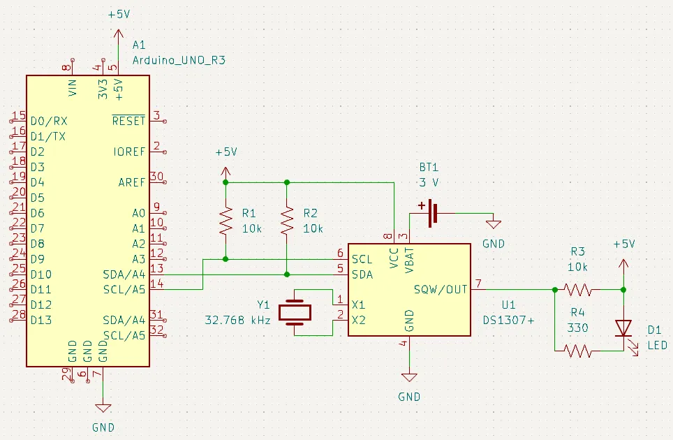
Schematic (Typical Operating Circuit)
Note that the backup supply is a 3V coin cell. This supply will allow the DS1307 to keep track of time when it is turned off.
The I2C communication lines require 10k pullup resistors. This is so they are not floating and can always have a known state.
The SQW output also has a 10k pullup. This is because the pin is open drain and can’t directly drive other electronics. Without proper external circuitry, it will also float like the I2C pins.
The DS1307 keeps track of time by reading ticks from an oscillator. This is why a 32.768 kHz oscillator (Y1) is attached to pins 1 and 2.
Library
This project uses my DS130X library. Download the library in Zip format
Using the SQW Output
In this example, we will use the SQW output on the DS1307. The LED circuit is included in the schematic above.
Note the use of the 10k resistor - this is the pullup resistor required for the SQW output.
The SQW pin is used as a current sink - the LED’s anode is connected to 5V and the cathode is connected to R4, then the SQW pin. This is because the output is open-drain, so it can only be used to sink current.
The example code is at .
/*
   SquareWave.ino
   Sketch to demonstrate the square wave output of the DS1307.
   Created August 29, 2020

   The DS1307 has a Square Wave output pin (#7). This pin can provide six frequencies:
   Continuous Off : SQW_LOW
   1 Hz           : SQW_1HZ
   4.096 kHz      : SQW_4KHZ
   8.192 kHz      : SQW_8KHZ
   32.768 kHz     : SQW_32KHZ
   Continuous On  : SQW_HIGH

   To use this output, first call setHalt(false) to enable the oscillator.
   Then, use writeRaw [not write()] to write to the SQW_OUT register.
   For a desired frequency, use the constant listed next to the frequency
   above.
*/

#include <DS130X.h>
#include <Wire.h>

DS1307 rtc;

void setup() {
  Wire.begin();
  Serial.begin(9600);
  rtc.setHalt(false); // Enable internal oscillator (needed for working output)
}

void loop() {
  // Output high
  Serial.println("SQW High");
  rtc.writeRaw(SQW_OUT, SQW_HIGH);
  delay(5000);

  // Output 1 Hz
  Serial.println("SQW 1 Hz");
  rtc.writeRaw(SQW_OUT, SQW_1HZ);
  delay(5000);

  // Output 4.096 kHz
  Serial.println("SQW 4.096 kHz");
  rtc.writeRaw(SQW_OUT, SQW_4KHZ);
  delay(5000);

  // Output 8.192 kHz
  Serial.println("SQW 8.192 kHz");
  rtc.writeRaw(SQW_OUT, SQW_8KHZ);
  delay(5000);

  // Output 32.768 kHz
  Serial.println("SQW 32.768 kHz");
  rtc.writeRaw(SQW_OUT, SQW_32KHZ);
  delay(5000);

  // Output off
  Serial.println("SQW Off");
  rtc.writeRaw(SQW_OUT, SQW_LOW);
  delay(5000);
}
Serial monitor output
SQW High
SQW 1 Hz
SQW 4.096 kHz
SQW 8.192 kHz
SQW 32.768 kHz
SQW Low
Setting the Frequency
To use the SQW pin, we first need to enable the internal oscillator. This done with setHalt(false);.
To set the square wave frequency, use writeRaw to write to the register SQW_OUT. For the data to write, use one of the constants:
SQW_HIGH: Output onSQW_1HZ: 1 Hz square waveSQW_4KHZ: 4.096 kHz square waveSQW_8KHZ: 8.192 kHz square waveSQW_32KHZ: 32.768 kHz square waveSQW_LOW: Output off
Important | Be sure to use writeRaw (not write) to set the frequency. The constant values are in the raw BCD format. |
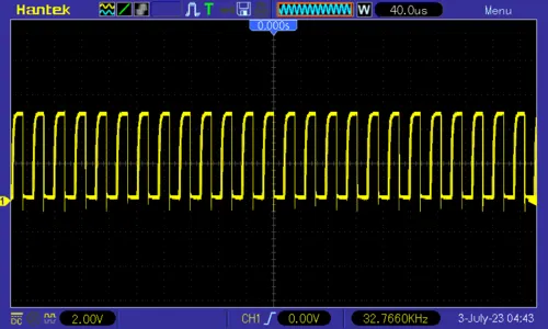
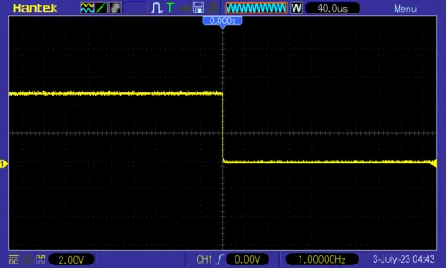
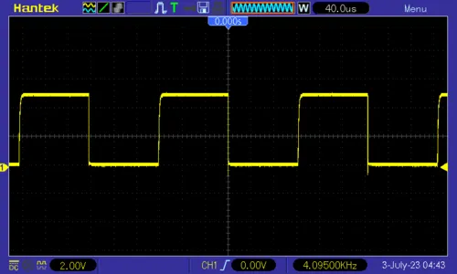
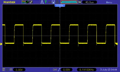
Output Waveforms
Below are oscilloscope screenshots of the various wave frequencies:
1 Hz
4.096 kHz
8.192 kHz
32.768 kHz