L293D Motor Driver with Arduino

Published
Controlling a motor from an Arduino using the L293D H-bridge
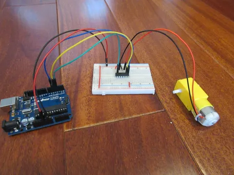
Driving a Motor with Arduino
A good way to control a motor is to use an H-bridge. This is a type of circuit that allows you to reverse the current flow of the motor, therefore giving you direction control.
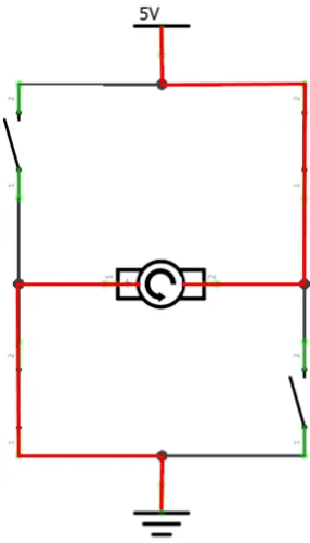
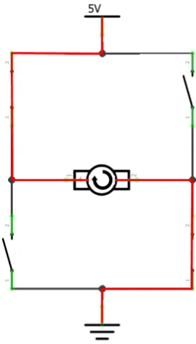
An H-bridge contains four switches and a motor at the center, forming an H-like shape. Turning any two of the switches on reverses the motor’s current, which can change its direction.
| Direction 1 | Direction 2 |
|---|---|
 |  |
The L293D has two of these H-bridges inside it, allowing you to control up to two DC motors or one stepper motor.
L293D Pinout
| Pin | Pin name |
|---|---|
1 | Enable 1 |
2 | Input 1 |
3 | Output 1 |
4 | GND |
5 | |
6 | Output 2 |
7 | Input 2 |
8 | VCC2 |
9 | Enable 2 |
10 | Input 3 |
11 | Output 3 |
12 | GND |
13 | |
14 | Output 4 |
15 | Input 4 |
16 | VCC1 |
The pins with names containing the same numbers form a single channel in the L293D that can control one motor.
Each pin type has a specific function:
Enable pins turn the motor on/off and control its speed.
Input pins control the direction of the motor.
Output pins connect to the motor to drive it.
GND pins are ground connection pins.
Pin 8 is the motor power connection.
Pin 16 is the IC power connection.
Controlling L293D
The Enable pins turn their motors on/off. A HIGH state enables the motor; a LOW state disables it. You can also send PWM signals to control motor speed. A duty cycle of 0% stops the motor; a duty cycle of 100% runs the motor at full speed.
The input pin pairs of the H-bridge control the direction of their motor. If input A is high and input B is low, the motor spins one direction. If input A is low and input B is high, the motor spins in the opposite direction. If the inputs' states are the same, the motor stops.
H-Bridge control summary:
| Input (Enable, In A, In B) | Motor Direction/Speed |
|---|---|
0, any, any | Stopped |
1, 1, 1 | Stopped |
1, 1, 0 | Direction 1 |
1, 0, 1 | Direction 2 |
1, 0, 0 | Stopped |
PWM, any, any | Varied speed |
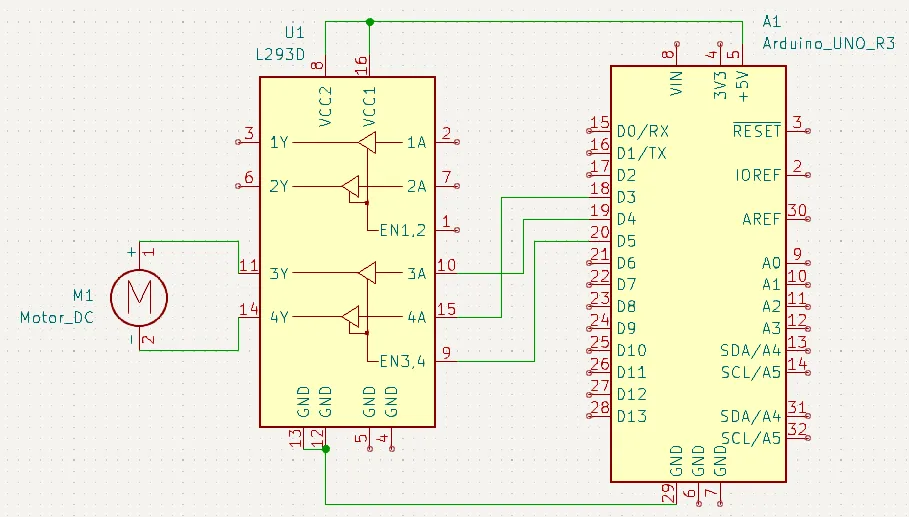
Schematic

Example Code
// Define pin constants
#define EN  5
#define IN1 4
#define IN2 3

boolean isReversed = false;

void setup() {
  // Configure pins as output
  pinMode(EN,  OUTPUT);
  pinMode(IN1, OUTPUT);
  pinMode(IN2, OUTPUT);
}

void loop() {
  for (int i = 0; i < 256; i++) {
    // Increment the speed from 0 to 255
    setMotorSpeed(i, isReversed);
    delay(10);
  }

  delay(3000); // Run at full speed for 3 seconds

  for (int i = 255; i > 0; i--) {
    // Decrement the speed from 255 to 0
    setMotorSpeed(i, isReversed);
    delay(10);
  }

  // Stop the motor and wait a little bit
  stopMotor();
  delay(2000);
  isReversed = !isReversed; // Reverse the motor
}

// Motor control functions

void setMotorSpeed(int speed, boolean reverse) {
  // Set the speed of the motor.
  analogWrite(EN, speed);
  digitalWrite(IN1, reverse);
  digitalWrite(IN2, !reverse);
}

void stopMotor() {
  // Stop the motor.
  analogWrite(EN, 0);
  digitalWrite(IN1, LOW);
  digitalWrite(IN2, LOW);
}