DS1302 RTC with Arduino
Published
Using the DS1302 real-time clock (RTC) with Arduino
Date/time and RAM examples are listed in the DS130X Common Reference. This page covers DS1302-specific features.
DS1302 Features
The DS1302:
Consumes little power.
Stores data in the binary-coded decimal (BCD) format.
Has 31 bytes of non-volatile static RAM (SRAM). When power is lost, the data in RAM won’t be lost.
Operates using a three-wire serial interface.
Holds information for seconds, minutes, hours, day of month, day of week, month, and year.
Automatically corrects the date information at the end of a month and provides leap year correction.
Can be run in 12 hour (1:00-12:00 with AM/PM flag) or 24 hour mode (0:00-23:00).
Can trickle-charge its battery by outputting voltage from its VCC1 pin.
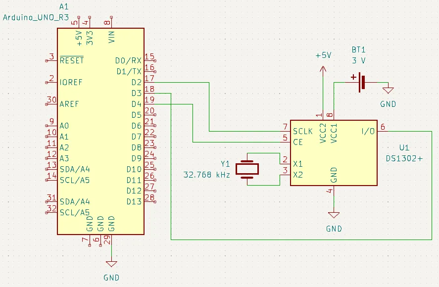
| Pin | Pin name | Function |
|---|---|---|
1 | VCC2 | 5V power supply |
2 | X1 | Connection to 32.768 kHz quartz crystal |
3 | X2 | |
4 | GND | Ground |
5 | CE | Chip enable |
6 | I/O | Serial data |
7 | SCLK | Serial clock |
8 | VCC1 | Connection to 3V battery |
Schematic (Typical Operating Circuit)
Note that the backup supply is a 3V coin cell. This supply will allow the DS1302 to keep track of time when it is turned off.
The DS1302 keeps track of time by reading ticks from an oscillator. This is why a 32.768 kHz oscillator (Y1) is attached to pins 1 and 2.
Library
This project uses my DS130X library. Download the library in Zip format
Using the TCR (Trickle Charge Register)
Trickle charging means to charge a battery at the same rate as its discharge rate, so it remains at its current level. The DS1302 charges its battery by outputting voltage from its VCC1 pin.
The example code is at . It does not output anything to the serial monitor.
Caution | If you have a non-rechargeable battery (or if you don’t know if it’s rechargeable), take it out before running this example. Attempting to charge a non-rechargeable battery can cause it to catch fire or explode. You can use a multimeter to measure the voltage between VCC1 and GND to make sure this function works. |
/*
   SetTCR.ino
   Sketch to demonstrate using the DS1302's trickle charge feature.
   Created August 30, 2020

   DS1302 connections:
   CLK to 2
   DAT to 3
   CE  to 4
*/

#include <DS130X.h>

DS1302 rtc(3, 2, 4); // DAT, CLK, CE

void setup() {
  rtc.setWriteProtect(false); // Disable write protect
  rtc.writeRaw(TCR_SET, TCR_1D_2R); // Set TCR to 1 diode and 2kR
}

void loop() {} // No loop
DS1302 TCR Output Voltage/Current
The DS1302 outputs the same amount of voltage present on VCC2, the main power supply. In our circuit, the DS1302’s main power supply (the Arduino’s 5V pin) is 5V, so the TCR will also output 5V.
The DS1302’s TCR has internal resistors and diodes. Selecting how many of these are activated will change the output current.
You can select any combination of resistors and diodes from below:
1 or 2 diodes
2k, 4k, or 8k resistor
The formula for calculating the output current from the diodes/resistors is:
: Output current (A)
: Diode drop, e.g., voltage drop across a diode (typically 0.7 V); multiply this by the number of diodes you selected
: Resistor value you selected (Ω)
For example, the output current of having 1 diode and the 2k resistor selected would be:
Configuring the TCR
The DS1302 powers up with the TCR disabled. To enable the TCR, use writeRaw (not write) to write to the register TCR_SET. For the data to write, use one of these six constants:
TCR_DISABLE: TCR is disabledTCR_1D_2R: 1 diode and 2 kΩ resistanceTCR_1D_4R: 1 diode and 4 kΩ resistanceTCR_1D_8R: 1 diode and 8 kΩ resistanceTCR_2D_2R: 2 diodes and 2 kΩ resistanceTCR_2D_4R: 2 diodes and 4 kΩ resistanceTCR_2D_8R: 2 diodes and 8 kΩ resistanceTCR_INITIAL: Initial power-on state (also disabled)
For example, to set the TCR to have 1 diode and a 2k resistor to have a 2.2mA current (like described above), use:
rtc.writeRaw(TCR_SET, TCR_1D_2R);Note | To get the current TCR setting, read from the TCR_GET register. readRaw is preferred since it returns the raw BCD data, like how writeRaw writes raw data. |
In the code, The Arduino will disable the RTC’s write protect, then write to the TCR_SET register with data TCR_1D_2R (1 diode, 2k resistor).