ADS1115 with Raspberry Pi
Published
Measuring analog values with a Raspberry Pi and ADS1115 ADC
The ADS1115
The ADS1115 is an ADC (Analog-to-Digital Converter). ADCs convert analog signals (like sine waves) into digital signals through communication protocol like SPI or I2C. They are used to give analog inputs to a device incapable of measuring analog signals by itself, such as Raspberry Pis.
Below are some specifications for the ADS1115:
Operating voltage: 2.0 V-5.5 V
Current consumption: 150 µA in continuous mode
Communication protocol: I2C
Programmable data rate: 8-860 SPS (Samples Per Second)
Precision: 16 bits
Number of channels (analog inputs): 4
Programmable comparator
Internal oscillator
Internal low-drift reference voltage
Four single-ended or two differential inputs
Programmable gain
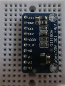
ADS1115 Pinout
| Pin | Description |
|---|---|
VDD | ADC power in connection |
GND | ADC ground connection |
SCL | I2C pin (serial clock) |
SDA | I2C pin (serial data) |
ADDR | Address selection pin |
ALRT | Alert/Ready signal connection |
A0 | Analog input 0 |
A1 | Analog input 1 |
A2 | Analog input 2 |
A3 | Analog input 3 |
ADS1115 Addressing
There are four addresses available. They are set by connecting the ADDR pin to either VDD, GND, SDA, or SCL.
| Connect ADDR to | Address |
|---|---|
GND | 0x48 (0b1001000) |
VDD | 0x49 (0b1001001) |
SDA | 0x4A (0b1001010) |
SCL | 0x4B (0b1001011) |
Note | The default address, when ADDR is not connected, is 0x48. |
ADS1115 Resolution
The output of the ADS1115 is a signed integer (positive or negative). This means that although the precision of the ADC is 16 bits, only 15 bits are used for the value of voltage measurements. One of the bits determines the sign of the value. So, there are 32,768 possible output values (0 to 32,767, or to binary).
ADS1115 Full Scale and Value of a Bit
The value of a bit is determined by the Programmable Gain Amplifier (PGA) setting. This setting establishes the full scale. In the default mode, the setting is ±6.144 V where 32,767 represents an input value of 6.144 V. Dividing 6.144 V by 32,767 yields a scale factor of 0.1875 mV per bit. You can also change the PGA setting to have a smaller full scale of ±2.048 V. That provides a more precise resolution of 0.0635 mV per bit.
Important | The maximum analog input voltage cannot exceed the voltage at VDD + 0.3 V. For example, if VDD is 3.3 V, the analog inputs cannot exceed 3.6 V. If the input does exceed 3.6 V, the chip on the ADS1115 could be damaged. |
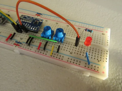
Schematic
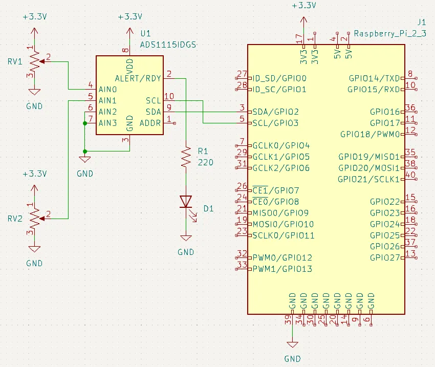
Note | It is a good idea to tie any unused inputs to ground to avoid "floating" inputs, where an input pin gives erratic readings, due to the fact that it is not connected to anything. |
Enabling I2C
Since the ADS1115 communicates over I2C, your Raspberry Pi needs I2C to be enabled. Follow the steps below if you haven’t already enabled I2C:
Go to the Raspberry Pi configuration tool with
sudo raspi-config.Use the arrow and Enter keys to go to Interfacing Options.
Go to I2C.
When the "Would you like the ARM I2C interface to be enabled?" message appears, select Yes.
Python Library
Below is a simple Python 3 library to use the ADS1115. Save it on your Raspberry Pi as ads1115.py:
# ads1115.py
# Python script to interface with ADS1115 ADC with Raspberry Pi.
# Created on 24 April 2020 by Aidan Sun

import smbus
import time

# Get I2C bus
bus = smbus.SMBus(1)

# I2C address of the device
ADS1115_DEFAULT_ADDRESS = 0x48

# ADS1115 Register Map
ADS1115_REG_POINTER_CONVERT   = 0x00
ADS1115_REG_POINTER_CONFIG    = 0x01
ADS1115_REG_POINTER_LOWTHRESH = 0x02
ADS1115_REG_POINTER_HITHRESH  = 0x03

# ADS1115 Configuration Register
ADS1115_CONFIG_SINGLE          = 0x8000
ADS1115_REG_CONFIG_MODE_CONTIN = 0x00
ADS1115_CONFIG_COMP_WINDOW     = 0x10
ADS1115_CONFIG_COMP_ACTVHI     = 0x08
ADS1115_CONFIG_COMP_LATCH      = 0x04
ADS1115_REG_CONFIG_CQUE_NONE   = 0x03

GAIN_2_3 = 0
GAIN_1   = 1
GAIN_2   = 2
GAIN_4   = 3
GAIN_8   = 4
GAIN_16  = 5

SPS_8    = 0
SPS_16   = 1
SPS_32   = 2
SPS_64   = 3
SPS_128  = 4
SPS_250  = 5
SPS_475  = 6
SPS_860  = 7

DIFF_0_1 = 0
DIFF_0_3 = 1
DIFF_1_3 = 2
DIFF_2_3 = 3

class ADS1115:
    """Class for interfacing with ADS1115"""
    def __init__(self, device_address=ADS1115_DEFAULT_ADDRESS, gain=GAIN_1, sps=SPS_128):
        # Set up address, gain, and SPS values
        gain_vals  = [0x00, 0x02, 0x04, 0x06, 0x08, 0x0A]
        sps_vals   = [0x00, 0x20, 0x40, 0x60, 0x80, 0xA0, 0xC0, 0xE0]

        self._addr = device_address
        self._gain = gain_vals[gain]
        self._sps  = sps_vals[sps]

    def read_adc(self, ch):
        """Reads a channel from the ADC. The ch parameter must be between 0 and 3.
        Returns the value as a 16-bit integer.
        """

        # Check if ch is valid
        if not(0 <= ch <= 3):
            raise ValueError("Channel must be between 0 and 3")

        channels = [0x40, 0x50, 0x60, 0x70]
        config = [ADS1115_CONFIG_SINGLE | channels[ch] | self._gain | ADS1115_REG_CONFIG_MODE_CONTIN, self._sps | ADS1115_REG_CONFIG_CQUE_NONE]
        bus.write_i2c_block_data(self._addr, ADS1115_REG_POINTER_CONFIG, config)
        time.sleep(0.02)
        data = bus.read_i2c_block_data(self._addr, ADS1115_REG_POINTER_CONVERT, 2)

        # Convert the data
        adc_data = (data[0] * 256) + data[1]
        return adc_data if adc_data <= 32767 else adc_data - 65535

    def read_adc_differential(self, ch):
        """Reads the difference between two ADC channels.
        Returns the value as a 16-bit integer.
        """

        # Check if ch is valid
        if not(0 <= ch <= 3):
            raise ValueError("Channel must be between 0 and 3")

        channels = [0x00, 0x10, 0x20, 0x30]
        config = [ADS1115_CONFIG_SINGLE | channels[ch] | self._gain | ADS1115_REG_CONFIG_MODE_CONTIN, self._sps | ADS1115_REG_CONFIG_CQUE_NONE]
        bus.write_i2c_block_data(self._addr, ADS1115_REG_POINTER_CONFIG, config)
        time.sleep(0.02)
        data = bus.read_i2c_block_data(self._addr, ADS1115_REG_POINTER_CONVERT, 2)

        # Convert the data
        adc_data = (data[0] * 256) + data[1]
        return adc_data if adc_data <= 32767 else adc_data - 65535

    def read_adc_comparator(self, ch, low_thresh, high_thresh, active_low=True, traditional=True, latching=False, num_readings=1):
        """Read an ADC channel with comparator enabled"""

        # Check if num_readings is valid
        if num_readings not in [1, 2, 4]:
            raise ValueError("num_readings must be 1, 2, or 4")

        comp_que = [None, 0, 1, None, 2]
        bus.write_i2c_block_data(self._addr, 0x02, [low_thresh >> 8, low_thresh & 0xFF])
        bus.write_i2c_block_data(self._addr, 0x03, [high_thresh >> 8, high_thresh & 0xFF])

        config = ADS1115_CONFIG_SINGLE | ((ch + 0x04) << 12) | self._gain | 0x0100 | self._sps

        if not traditional:
            config |= ADS1115_CONFIG_COMP_WINDOW

        if not active_low:
            config |= ADS1115_CONFIG_COMP_ACTVHI

        if latching:
            config |= ADS1115_CONFIG_COMP_LATCH
        config |= comp_que[num_readings]

        bus.write_i2c_block_data(self._addr, ADS1115_REG_POINTER_CONFIG, [config >> 8, config & 0xFF])
        time.sleep(0.02)
        data = bus.read_i2c_block_data(self._addr, ADS1115_REG_POINTER_CONVERT, 2)

        # Convert the data
        adc_data = (data[0] * 256) + data[1]
        return adc_data if adc_data <= 32767 else adc_data - 65535
Note | To learn more about the specific I2C values and how they should be sent to the ADS1115, go to its datasheet. |
Reading Channels
The code below reads each analog input and prints their values:
from ads1115 import *

a = ADS1115()

while True:
    # Loop infinitely
    try:
        # Print readings into rows
        print(a.read_adc(0), end="\t")
        print(a.read_adc(1), end="\t")
        print(a.read_adc(2), end="\t")
        print(a.read_adc(3), end="\n")
    except KeyboardInterrupt:
        # Exit loop
        print("\nProgram Stopped")
        break
Output
18      18      18      18
18      18      18      18
18      18      18      18
18      18      18      18
18      18      17      17
18      18      19      17
18      18      18      17
18      18      18      18
18      18      18      18
18      18      18      18
18      18      18      18
18      18      18      18
103     18      18      18
1743    18      18      18
5187    18      18      18
7611    18      18      18
10342   18      18      17
5404    18      18      18
13097   18      18      19
20431   18      19      19
20430   18      19      19
20427   18      19      18
20431   18      18      17
20887   18      18      18
Program Stopped
There should be an output with four columns, A0 reading on the left to A3 reading on the right. Rotate the trimpot connected to A0 to make the first value change.
Explanation
After importing the library, we create an ADS1115 instance. The ADS1115 constructor also accepts the following keyword arguments:
device_address: ADC address (default is 0x48)gain: Gain value, possible values:GAIN_2_3, gain of ± 6.144 VGAIN_1- gain of ± 4.096 V (default)GAIN_2- gain of ± 2.048 VGAIN_4- gain of ± 1.024 VGAIN_8- gain of ± 0.512 VGAIN_16- gain of ± 0.256 V
sps: Data rate in samples per second (SPS), possible values:SPS_8- 8 SPSSPS_16- 16 SPSSPS_32- 32 SPSSPS_64- 64 SPSSPS_128- 128 SPS (default)SPS_250- 250 SPSSPS_475- 475 SPSSPS_860- 860 SPS
For example, to initialize the ADS1115 with address 0x49, gain of ± 2.048 V, and data rate of 250 SPS, you would use:
a = ADS1115(device_address=0x49, gain=GAIN_2, sps=SPS_250)In the infinite loop, we read from each of the four channels with read_adc. This method reads from a single ADC channel and takes the following parameter:
ch: The channel to read from (0 reads from A0, 1 reads from A1, etc.)
If a KeyboardInterrupt is caught, the program prints a message and exits.
Reading Differential Inputs
The following code reads the differential input between A0 and A1:
from ads1115 import *

a = ADS1115()

while True:
    try:
        print(a.read_adc_differential(DIFF_0_1))
    except KeyboardInterrupt:
        print("\nProgram Stopped")
        break
Output
2725
2749
2631
2534
2381
2137
1451
1437
1301
1033
772
47
52
88
42
40
32
13
12
12
Program Stopped
The output should have one column. Rotate both trimpots to see how the value changes.
Explanation
This ADS1115 library supports reading differential inputs with read_adc_differential. This method reads from two ADC channels and returns the difference. It accepts one parameter:
ch: Which two channels to read
Possible values:
DIFF_0_1returns channel 0 minus channel 1DIFF_0_3returns channel 0 minus channel 3DIFF_1_3returns channel 1 minus channel 3DIFF_2_3returns channel 2 minus channel 3
In the example code, we use DIFF_0_1, which makes the method return A0 reading minus A1 reading. The loop and exception handling parts are the same as the first example.
Using the Comparator
About the ADS1115 Comparator
The ADS1115 has a built-in comparator. This comparator has two modes: traditional and window.
In traditional mode, the ADS1115 activates the ALRT pin if the input of a channel goes above a specified high threshold. The ALRT pin gets deactivated when the reading drops below a specified low threshold.
In window mode, the ALRT pin activates when the reading is outside the range of the two thresholds. The ALRT pin gets deactivated when the reading is in the range of the two thresholds.
Code
from ads1115 import *

a = ADS1115()

while True:
    try:
        print(a.read_adc_comparator(0, 2000, 10000)) # Traditional mode
        # print(a.read_adc_comparator(0, 2000, 10000, traditional=False)) # Window mode
        # print(a.read_adc_comparator(0, 2000, 10000, active_low=False)) # Traditional mode with active high
    except KeyboardInterrupt:
        print("\nProgram Stopped")
        break
Explanation
To read the ADS1115 comparator, use read_adc_comparator. This method accepts the following parameters:
ch: Channel to read fromlow_thresh: Low thresholdhigh_thresh: High thresholdactive_low: State of the ALRT pin: active low if True, active high if False (optional, default is True)traditional: Mode of the comparator: traditional if True, window if False (optional, default is True)latching: If the comparator is latching: latching if True, not latching if False (optional, default is False)num_readings: Number of readings the ADC reads before changing the state of the ALRT pin (optional, default is 1)
In the example code, low_thresh is set to 2000 and high_thresh is set to 10000. All optional parameters are left alone.
This example code by default uses the comparator in traditional mode. Play the video below to see how the LED should change in traditional mode.
To use window mode, uncomment line 8 and comment line 7. Run the code again, and you should see the LED turn on when it is inside the 2000-10000 range:
To set the ALRT pin to active high, uncomment the third read_adc_comparator line (line 9) and comment the other two.
Active high can be used with both comparator modes. Combine traditional=False with active_low=False to have the pin active high in window mode.
If you run the code again, you should see that the LED’s state is inverted: