Rotary Encoder with Arduino
Published
Using an incremental rotary encoder with Arduino
How the Rotary Encoder Works
The rotary encoder used in this article is an incremental encoder which provides information about its knob’s rotation. It is up to the controller to turn the measurements into useful values such as distance and speed.
The knob is attached to a disc inside the encoder. There are also two contact points placed next to the spinning disc. These are the A and B outputs of the encoder. When the disc spins, the points remain stationary. This causes them to alternate between touching GND and VCC, producing square waves.
The placement of the contacts causes the waves to be 90 degrees out of phase. If the knob rotates clockwise, the B pin will lead. If the knob rotates counter-clockwise, then the A pin will lead. This is how we tell what direction the encoder is turning.
Some rotary encoders also have a switch under the knob that allows it to be pressed. This switch is connected to an additional SW pin.
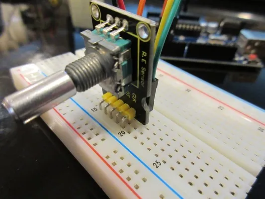
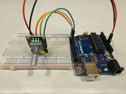
Pin Connections
A rotary encoder module usually has the following pins. Their connections to the Arduino in the code are also provided in the table.
| RE module pin | Stands for | Description | Connects to Arduino pin |
|---|---|---|---|
CLK | Clock | Encoder output 1 | Digital pin 4 |
DT | Data | Encoder output 2 | Digital pin 3 |
SW | Switch | Switch connection | Digital pin 2 |
+ (VCC) | Power in | Power connection | 5V pin |
- (GND) | Ground | Ground connection | GND pin |
Code
// Pin constants
#define A_PIN      4
#define B_PIN      3
#define BUTTON_PIN 2

int state, lastState, counter;

void setup() {
  Serial.begin(9600);
  pinMode(A_PIN, INPUT);
  pinMode(B_PIN, INPUT);
  pinMode(BUTTON_PIN, INPUT);

  // Read initial
  lastState = digitalRead(A_PIN);
}

void loop() {
  state = digitalRead(A_PIN); // Read output of output A
  if (state != lastState) {
    // State has changed, so a pulse has occurred
    // If the outputB state is different to the outputA state, that means the encoder is rotating CW
    if (digitalRead(B_PIN) != state) {
      // Two output states are different, so encoder is rotating CW
      counter++; // Increment counter
    } else {
      counter--; // Rotating CCW, decrement counter
    }
  }
  int btn = digitalRead(BUTTON_PIN); // Read button
  lastState = state; // Update last state

  // Print values
  Serial.print("Counter: "); Serial.print(counter); // Print the counter
  Serial.print(" Button: "); Serial.println(btn);   // Print button state
}
We start by defining the pins that the encoder is connected to, as well as open a serial port and configure the pins as inputs. We also read the initial state of the encoder.
In the loop function, we start by reading the current state of the encoder. If there is a difference between the old and current states, a pulse has occurred (the user rotated the knob.) We then check if the B output is different from the A output. If it is, then the encoder is rotating clockwise and we increment the counter. Otherwise, we decrement the counter.
Outside the if blocks, we also read the button pin and update the last reading. We then use Serial.print and Serial.println to output the values to the serial monitor.
Testing
Upload the code to the Arduino and open the serial monitor. Test the code by rotating the encoder and pressing the button. The displayed numbers should change accordingly to the rotation of the knob. Be sure to not rotate it too fast, as the Arduino may not read the pulses fast enough.
Serial monitor output
Counter: 26 Button: 1
Counter: 26 Button: 1
Counter: 27 Button: 1
Counter: 28 Button: 1
Counter: 29 Button: 1
Counter: 30 Button: 0
Counter: 32 Button: 0
Counter: 29 Button: 0
Counter: 27 Button: 0
Counter: 25 Button: 1