Arduino Clock
Published
A simple alarm clock with an Arduino Nano
Overview
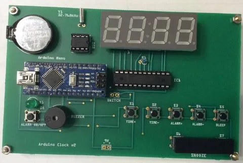
The Arduino Clock v2 is an open-source, easy-to-use alarm clock running on an Arduino Nano. It features a bright 4-digit seven-segment display with decimal points, large snooze button, and two ways to be powered - USB or battery.
Specifications
| Attribute | Value |
|---|---|
Microcontroller | ATmega328P (on Arduino Nano) |
Input Voltage | 5V DC via USB or 7-12V DC via input pins |
Clock Speed (crystal) | 16MHz microcontroller, 32.768kHz DS1302 |
PCB Size | 13.3 cm ⨯ 8.3 cm (5.2 in ⨯ 3.2 in) |
Clock Chip | DS1302 |
Clock Chip Backup Power Supply | 3V DC via coin cell battery |
Num. of Digits | 4 |
Mounting Holes | 4 |
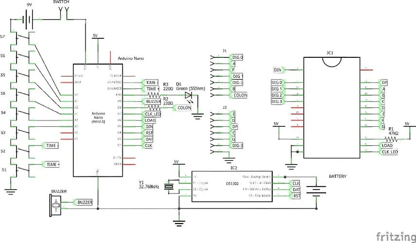
Schematic

List of Parts
All IC sockets have 300 mil pin spacing.
| Part | Symbol | Quantity |
|---|---|---|
Arduino Nano v3 | Arduino Nano | 1 |
4-Digit 7-Segment Display | 1 | |
MAX7219 | IC1 | 1 |
DS1302 | IC2 | 1 |
32.768kHz crystal | Y1 | 1 |
Pushbutton (normally open) | S1-8 | 8 |
Buzzer | BUZZER | 1 |
DIP24 IC socket | 1 | |
DIP8 IC socket | 1 | |
Green LED | D1 | 1 |
Female header, 15 pins | 1 | |
Rounded female header, 7 pins | 2 | |
47k resistor | R1 | 1 |
220R resistor | R2-3 | 2 |
3V coin cell holder | 1 | |
9V battery snap (optional) | 1 | |
SPST slide switch (optional) | 1 | |
9V battery (optional) | 1 | |
3V coin cell (CR2032) | 1 | |
Fabricated PCB | 1 |
Installation
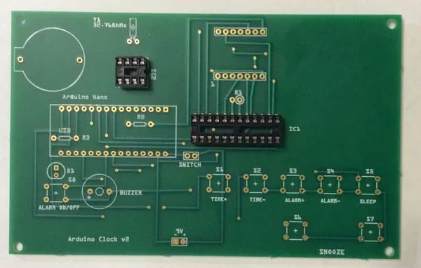 | Solder on both IC sockets. Pay attention to the orientation and direction of the notch. |
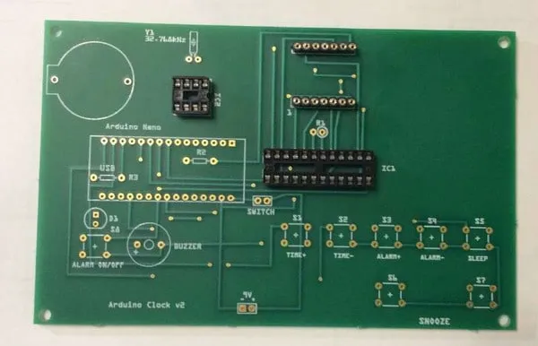 | Solder on both rounded female headers (7 pins). |
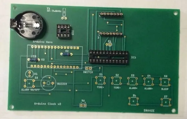 | Solder on the battery holder, R2, and R3 (both 220R). |
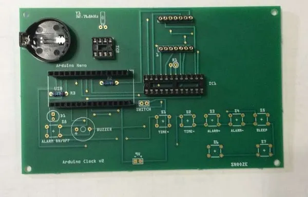 | Solder on both female headers (15 pins). |
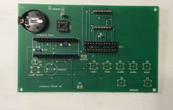 | R1 is mounted vertically to save space. Bend one of the leads 180 degrees to make it fit. Then, put it on the PCB with the actual resistor in the circle. Next, be sure to leave at least 2mm of lead space on Y1 at the top of the PCB. Solder on R1 and Y1. |
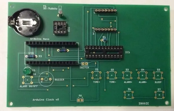 | Solder on D1. Make sure that the anode goes into the square pad. |
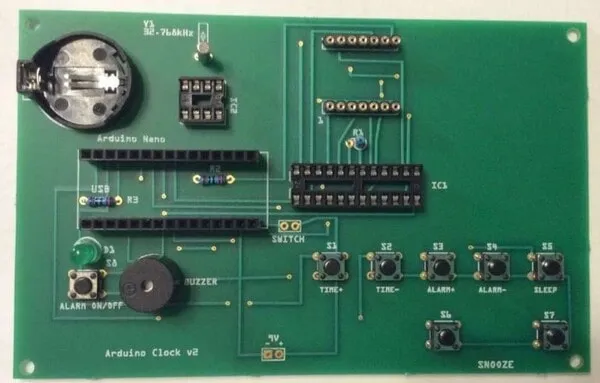 | Solder on S1-8 and the buzzer. Make sure that the "+" on the buzzer is on the left. |
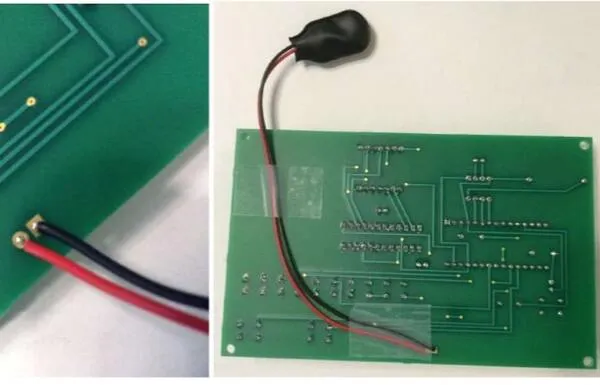 | If using 9V battery: Solder the 9V battery snap to the back of the PCB. The black wire should be in the square pad. Then, attach the wires to the board with tape. |
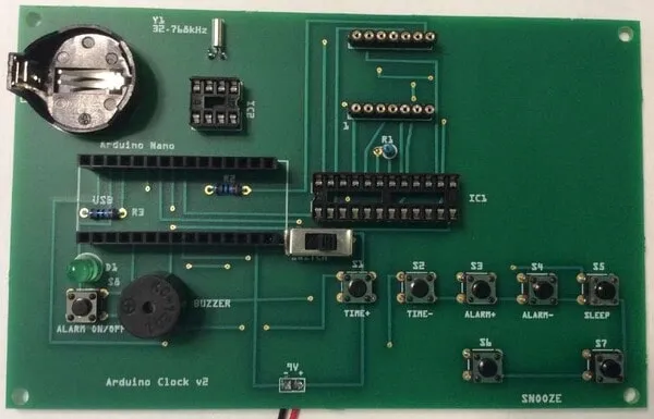 | If using 9V battery: Solder the SPST slide switch to the two holes labelled "SWITCH". |
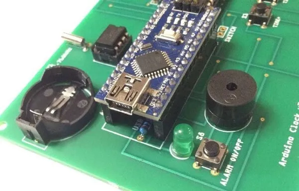 | Bend Y1 downward. Then, insert the Arduino Nano into the two long female headers. The USB port should be over the word "USB" on the PCB. |
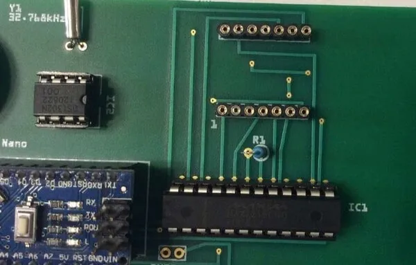 | Insert the two ICs into their corresponding sockets. Pay attention to their orientation. |
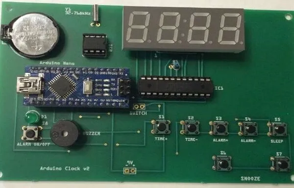 | Note the small "1" on the PCB. This indicates where pin 1 of the display should be connected. Insert the display into the rounded female headers. Then, insert a 3V coin cell into the coin cell holder. The side marked with a "+" should be on top. |
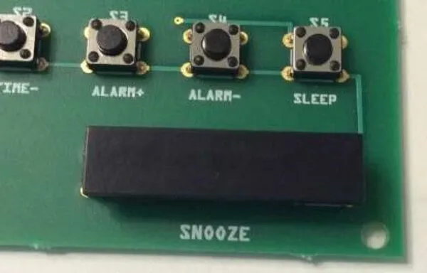 | Use superglue to stick a 7.5 mm ⨯ 31 mm (0.3 in ⨯ 1.2 in) piece of black, rigid plastic to S6 and S7, forming the snooze bar. |
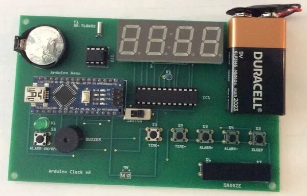 | If using 9V battery: Insert the 9V battery into the snap and use double-sided tape to stick it on the PCB. |
Code
Note | You will need the DS130X and LedControl libraries for the code to compile and run properly. |
// Keyboard shortcuts:
// TIME+ and ALARM+  loads alarm time
// TIME- and ALARM-  saves alarm time
// TIME+ and SLEEP   clears alarm time

#include <DS130X.h>     // RTC
#include <LedControl.h> // MAX7219
#include <EEPROM.h>     // EEPROM

// Pin definitions

// RTC Pins
#define RTC_CLK 2 // CLK pin on DS1302
#define RTC_DAT 3 // DAT pin on DS1302
#define RTC_RST 4 // RST pin on DS1302

// LED Pins
#define LED_DIN    5 // DIN pin on MAX7219
#define LED_CS     6 // LOAD pin on MAX7219
#define LED_CLK    7 // CLK pin on MAX7219
#define COLON      8 // Pin 8 on LED display
#define INDICATOR 10 // LED to indicate if alarm is on

// Button pins
#define TIME_PLUS    11
#define TIME_MINUS   12
#define SNOOZE_1     14
#define SNOOZE_2     15
#define SLEEP        16
#define ALARM_ON_OFF 17
#define ALARM_MINUS  18
#define ALARM_PLUS   19

#define BUZZER  9 // Buzzer pin

// Variables
DS1302 rtc(RTC_DAT, RTC_CLK, RTC_RST);
LedControl lc(LED_DIN, LED_CLK, LED_CS, 1);

int h, m, s; // Variables for time
int alarm_hr = 12;
int alarm_min = 0;
boolean alarm = false;
boolean pressed = false;
boolean prev = false;
boolean done = false;
int del = 250; // Milliseconds between time changes if the TIME +/- button is held down
int snooze_time = 5; // Minutes in between pressing snooze and alarm going off again

void setup() {
  // Configure digital pins
  // The pins A6/7 do not have internal pullup resistors; therefore, they are not used
  pinMode(COLON, OUTPUT);
  pinMode(INDICATOR, OUTPUT);
  pinMode(TIME_PLUS, INPUT_PULLUP);
  pinMode(TIME_MINUS, INPUT_PULLUP);
  pinMode(SNOOZE_1, INPUT_PULLUP);
  pinMode(SNOOZE_2, INPUT_PULLUP);
  pinMode(SLEEP, INPUT_PULLUP);
  pinMode(ALARM_ON_OFF, INPUT_PULLUP);
  pinMode(ALARM_MINUS, INPUT_PULLUP);
  pinMode(ALARM_PLUS, INPUT_PULLUP);
  pinMode(BUZZER, OUTPUT);

  // RTC setup
  rtc.setHalt(false); // Set the RTC to run mode
  rtc.setWriteProtect(false); // Disable write protection

  // MAX7219 setup
  const int displayBrightness = 8;
  lc.shutdown(0, false); // Turn off power saving and enable display
  lc.setIntensity(0, displayBrightness); // Set brightness (Possible values 0 to 15)
  lc.clearDisplay(0); // Clear the display
}

void loop() {
  // Get h, m, and s
  h = rtc.read(HOURS);
  m = rtc.read(MINUTES);
  s = rtc.read(SECONDS);

  check12h(); // Check the current time and adjust if necessary
  displayNum(getTens(h), getOnes(h), getTens(m), getOnes(m)); // Display the time

  if (not(digitalRead(SLEEP)) && done) {
    alarm = false; // no alarm
    digitalWrite(BUZZER, LOW);
  }

  if (((not(digitalRead(SNOOZE_1))) || (not(digitalRead(SNOOZE_2)))) && done) {
    // Snooze pressed, add 5 minutes
    alarm_min += snooze_time;
    check12hAlarm();
    digitalWrite(BUZZER, LOW); // turn buzzer off
    done = false; // not done yet
  }

  // Check if the Alarm On/Off button has been pressed
  pressed = !digitalRead(ALARM_ON_OFF);
  // Only adtivate/deactivate alarm once button is released
  if (pressed != prev) {
    if (pressed) {
      alarm = !alarm;
    }
  }
  prev = pressed;
  digitalWrite(INDICATOR, alarm); // Indicator to tell if alarm is on

  // Alarm setting/checking
  setAlarm();
  checkAlarm();

  // Flash colon
  if ((s % 2) == 0) {
    // Turn on the colon if the amount of seconds is even
    digitalWrite(COLON, HIGH);
  } else {
    // Turn off the colon if the amount of seconds is odd
    digitalWrite(COLON, LOW);
  }

  if (not(digitalRead(TIME_PLUS))) {
    // Time+ button is pressed
    // Check for keyboard shortcut
    if (not(digitalRead(ALARM_PLUS))) {
      // Load alarm time
      loadAlarmTime();
    }
    else if (not(digitalRead(SLEEP))) {
      // Clear alarm time (these two buttons are far apart so no accidental clearing)
      clearAlarmTime();
    }
    else {
      // Increment minutes
      m += 1; // Increment m
      adjustTime();
      rtc.setTime(h, m, 0); // Set the new time
      delay(del); // Delay between changes if the button is held down
    }
  }

  if (not(digitalRead(TIME_MINUS))) {
    // Time- button is pressed
    // Check for keyboard shortcut
    if (not(digitalRead(ALARM_MINUS))) {
      // Save alarm time
      saveAlarmTime();
    }
    else {
      m -= 1; // Decrement m
      adjustTime();
      rtc.setTime(h, m, 0); // Set the new time
      delay(del); // Delay between changes if the button is held down
    }
  }
}

int getTens(int num) {
  return int(num / 10);
}

int getOnes(int num) {
  return num % 10;
}

void displayNum(int d1, int d2, int d3, int d4) {
  lc.setDigit(0, 0, d1, false);
  lc.setDigit(0, 1, d2, false);
  lc.setDigit(0, 2, d3, false);
  lc.setDigit(0, 3, d4, false);
}

void check12h() {
  if (h > 12) {
    h -= 12;
  }
  else if (h == 0) {
    h = 12;
  }
}

void check12hAlarm() {
  if (alarm_hr > 12) {
    alarm_hr -= 12;
  }
  else if (alarm_hr == 0) {
    alarm_hr = 12;
  }
}

void setAlarm() {
  if (alarm) {
    if (!digitalRead(ALARM_PLUS) && !done) {
      alarm_min++;
      adjustAlarm();
      displayNum(getTens(alarm_hr), getOnes(alarm_hr), getTens(alarm_min), getOnes(alarm_min));
      delay(del + 150); // more time to see the set alarm before displaying current time
    }

    if (!digitalRead(ALARM_MINUS) && !done) {
      alarm_min--;
      adjustAlarm();
      displayNum(getTens(alarm_hr), getOnes(alarm_hr), getTens(alarm_min), getOnes(alarm_min));
      delay(del + 150);
    }
  }
}

void checkAlarm() {
  if ((((h == alarm_hr) && (m == alarm_min)) || done) && (alarm && !checkAlarmButtonPress())) {
    done = true;
    if ((s % 2) == 0) { // Turn on the alarm if the amount of seconds is even
      digitalWrite(BUZZER, HIGH);
    }
    else { // Turn off the alarm if the amount of seconds is odd
      digitalWrite(BUZZER, LOW);
    }
  }
}

boolean checkAlarmButtonPress() {
  return !digitalRead(ALARM_PLUS) || !digitalRead(ALARM_MINUS);
}

void adjustTime() {
  if (m == 60) {
    // Overflow in minutes, set minutes to 0 and increment hour
    m = 0;
    h++;
  }
  if (m < 0) {
    // Underflow in minutes, set minutes to 59 and decrement hour
    m = 59;
    h--;
  }
  check12h(); // adjust if necessary
}

void adjustAlarm() {
  if (alarm_min == 60) {
    // Overflow in minutes, set minutes to 0 and increment hour
    alarm_min = 0;
    alarm_hr++;
  }
  if (alarm_min == -1) {
    // Underflow in minutes, set minutes to 59 and decrement hour
    alarm_min = 59;
    alarm_hr--;
  }
  check12hAlarm(); // adjust if necessary
}

void saveAlarmTime() {
  // Index 0 is hour
  // Index 1 is minute
  EEPROM.update(0, alarm_hr); // Only write if it is a new time
  EEPROM.update(1, alarm_min);
}

void loadAlarmTime() {
  alarm_hr = EEPROM.read(0);
  alarm_min = EEPROM.read(1);
}

void clearAlarmTime() {
  // Reset alarm values to default (12:00)
  EEPROM.update(0, 12); // hour
  EEPROM.update(1, 0);  // minute
}
Usage
Power-On: Turn the clock on. If you are using a 9V battery, slide the switch to the "ON" position. If you are using USB power, connect the USB port to a 5V USB supply (ex. a computer’s USB port) via a mini-USB cable.
Time Adjustments: To adjust the displayed time, use the TIME+/TIME- buttons (S1 and S2). TIME+ will add 1 to the minutes, and TIME- will subtract 1 from the minutes. The clock uses 12-hour time. Even when you turn it off, the clock will still be recording the time because the DS1302 has the coin cell as a backup power supply.
Setting an Alarm: To set an alarm, press the ALARM ON/OFF button (S8). D1 will turn on. The default alarm time is 12:00. Adjusting the alarm time is similar to adjusting the normal time. Use the ALARM+/ALARM- buttons (S3 and S4).
Turning the Alarm Off: When the set alarm time is reached, the buzzer will beep continuously. Use the SLEEP button (S5) to turn the alarm off, or use the snooze bar (S6 and S7) to make the clock wait 5 minutes before beeping again. The snooze bar will work if either button is pressed. It will also work if both buttons are pressed.
Replacing the Coin Cell: To replace the 3V coin cell, first turn the clock off. Then, use pliers to bend the small metal tab on the left of the holder to release the coin cell. After removing the coin cell, put a new one in by putting the right edge in first and then pushing the left end down to secure it.