// Include libraries
#include <SPI.h>     // For SPI communication
#include <SD.h>      // For SD operations
#include <DS130X.h>  // For DS1307

// Global variables
DS1307 rtc;
File f;

void setup() {
  Serial.begin(9600); // Open a serial port

  // Init SD card
  Serial.print("Initializing SD card... ");

  if (!SD.begin(4)) {
    Serial.println("Failed.");
    while (1);
  }
  Serial.println("Done.");
}

void loop() {
  // Open success, start logging
  String line = rtc.timeStr() + ","; // Get the time and delimit with comma

  int reading = analogRead(A0);

  // Perform necessary calculations here
  //reading = (reading * 500) / 1023; // For LM35: value -> deg C

  line.concat(reading); // Append reading to line

  f = SD.open("log.txt", FILE_WRITE); // Open log.txt for writing
  f.println(line);      // Write to file
  Serial.println(line); // Print line to serial monitor
  f.close();            // Close file
  delay(1000);          // Delay 1 second
}ATmega 40 Board Data Logging

Published
Logging data and saving timestamps onto an SD card with the ATmega 40 Board
Overview
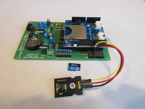
This guide uses the Arduino compatibility of the ATmega 40 Board to interface with an SD shield, allowing it to log and save data. Since the board contains an on-board RTC, it can also save timestamps of the data.
This project uses my DS130X library. Download the library in Zip format | DS130X Common Reference
See also: SD Shield, DS1307 with Arduino
Required Materials
ATmega 40 Board
SD Shield
Analog sensor of any kind (I used a LM35 module)
Blank SD/TF card (any size)
Jumper wires
Important | Your SD shield must have a female 2⨯3 header on the back, located on the underside. This will plug into the board’s ICSP header and allow it to communicate properly through SPI. |
Wiring
Using the jumper wires, connect the sensor to analog input A0. All analog inputs on the ATmega 40 Board are broken out with 5V and ground power rails for convenience.
Code
The first part of the code includes the required libraries and declares the global variables used for the program.
In the setup function, the ATmega 40 will open a serial port and attempt to initialize the SD card. It will then print out the results of initializing (failed or done). If the init succeeded, the ATmega 40 will continue to the loop function. If not, the ATmega 40 will do nothing through the while(1) loop.
In the loop function:
The ATmega 40 reads the current time and sensor reading.
If needed, you can add any calculations for your sensor on the highlighted lines. For example, the line to convert raw data to degrees C (for the LM35) is added in a comment.
The time and processed reading will be joined together into a single line, separated by a comma.
The file
log.txtwill be opened for writing. The ATmega 40 will write/print the line to both the file withf.println(line)and the serial monitor withSerial.println(line).Finally, the ATmega 40 will close the file to allow the changes to be made, then delay 1 second.
Running the Code
Before powering your board on, insert the SD card into the slot.
Upload and run the code. If you open the serial monitor, you will see the results of the SD initialization:
Initializing SD card... Done.
If you got "Failed." check the following:
Check that your SD card and shield both work.
The connections between the ATmega 40 Board and the shield should be secure. Look for the power LED on the shield, and make sure it is on.
The shield should have the black 2⨯3 header on the back. Without it, the shield won’t work with the ATmega 40 Board.
If you are using the SD Shield v3, the voltage switch should be set to 5V, not 3V3.
If the SD init is done, you will see the data being written to the serial monitor:
00:57:57,26
00:57:58,26
00:57:59,26
00:58:00,26
00:58:01,26
00:58:02,26
00:58:03,26
00:58:04,26
00:58:05,26
00:58:06,26
00:58:07,26
00:58:08,26
00:58:09,26
00:58:10,27
00:58:11,27
00:58:12,27
00:58:13,26
00:58:14,25
00:58:15,25
( ... )
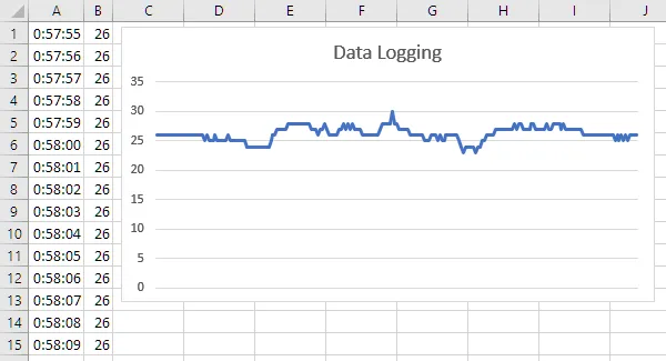
If you connect the SD card to your computer and open the file called LOG.TXT, you will see the data that the Arduino has logged, along with the timestamps. This is the same data that appears in the serial monitor.
By importing this data into a spreadsheet program, you can also see the graph of the logged data:
