| ATmega8535 | ATmega16 | ATmega32 | ATmega164 | ATmega324 | ATmega644 | ATmega1284 | Arduino Uno (ATmega328) | |
|---|---|---|---|---|---|---|---|---|
Operating Voltage | 5V | 5V | ||||||
Physical Pins | 40 | 28 | ||||||
I/O Lines | 32 | 23 | ||||||
ADC Ports | 8 | 6 | ||||||
PWM Channels | 4 | 6 | 8 | 6 | ||||
Flash Memory | 8k | 16k | 32k | 16k | 32k | 64k | 128k | 32k |
EEPROM | 512 | 1k | 512 | 1k | 2k | 4k | 1k | |
SRAM | 512 | 1k | 2k | 1k | 2k | 4k | 16k | 2k |
ATmega 40 Board
Published
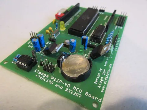
A development board for Atmel AVR microcontrollers, containing an on-board 74HC595 shift register and DS1307 RTC and using the Arduino standard pinout
Technical Details
This board is programmed using the Arduino IDE. This means that a lot of code written for an Arduino can be ported to this board (be aware of the memory sizes of the microcontrollers, compared in the table below).
This board is compatible with Atmel AVR microcontrollers in the DIP-40 package.
ATmega16
ATmega32
ATmega164
ATmega324
ATmega644
ATmega1284
ATmega8535
Microcontroller Comparison
Note that the ATmega328 is not compatible with the ATmega 40 Board - it has been displayed in this table for comparison purposes only.
Board Details
Microcontroller | ATmega16, 32, 164, 324, 644, 1284, 8535 |
Operating Voltage | 5V |
Input Voltage | 7-20V (recommended), 6-35V (limit) |
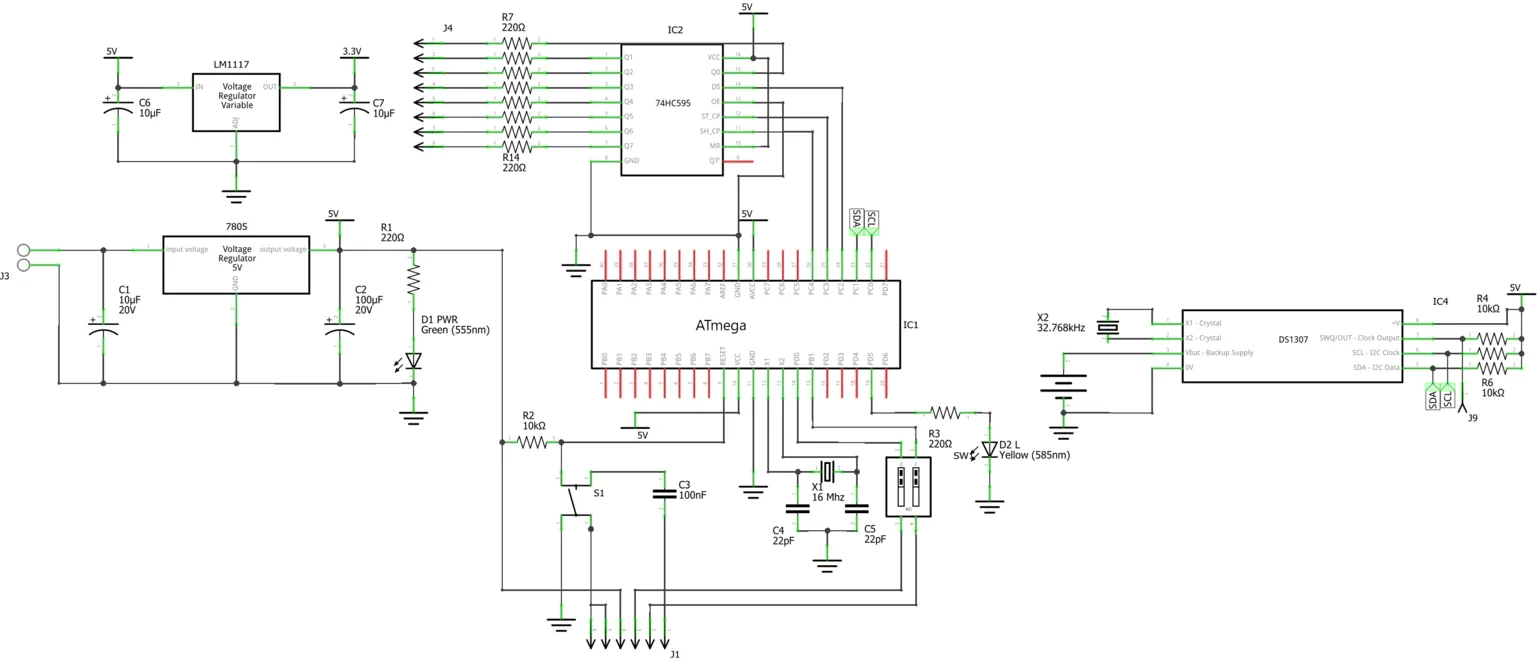
On-Board ICs | 74HC595 (shift register), DS1307 (RTC) |
Clock Frequency | 16MHz (microcontroller), 32.768kHz (RTC) |
"L" LED | 13 (PWM-enabled on all microcontrollers) |
Programming Interface | Serial (requires 5V FTDI cable) |
Length | 125.22 mm (4.93 in) |
Width | 78.66 mm (3.10 in) |
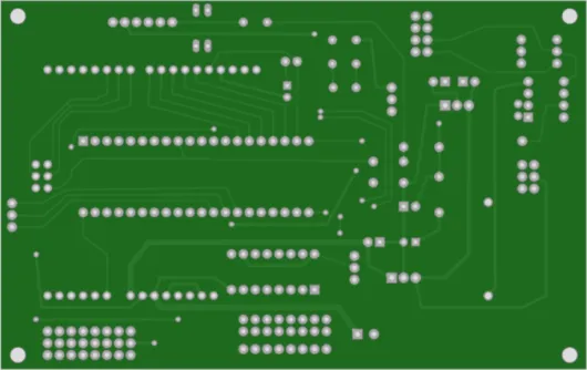
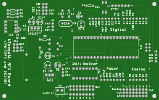
Board Pinout
Click to reveal large image

Schematic
Click to reveal large image
Parts List
Resistors

| Number | Part | Value | Quantity |
|---|---|---|---|
1 | Resistor | 10k | 4 |
2 | Resistor | 220R | 10 |
Passives
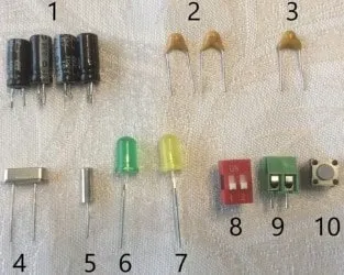
Number | Part | Value | Quantity |
1 | Electrolytic capacitor | 10µF | 4 |
2 | Ceramic capacitor | 20pF | 2 |
3 | 100nF | 1 | |
4 | Crystal oscillator | 16MHz | |
5 | 32.768kHz | ||
6 | 5mm LED | Green | |
7 | Yellow | ||
8 | DIP Switch | 2-Channel | |
9 | Screw Terminal | 2-Pin, 3.5mm spacing | |
10 | Pushbutton | Normally-Open |
Headers
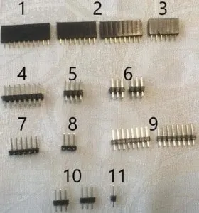
Number | Pin Type | # of Pins | Quantity |
1 | Female | 10 | 1 |
2 | 8 | 2 | |
3 | 6 | 1 | |
4 | Double-row male | 16 | |
5 | 8 | ||
6 | 6 | 2 | |
7 | Right-angle male | 1 | |
8 | 3 | ||
9 | Male | 8 | 2 |
10 | 3 | ||
11 | 1 | 1 |
ICs
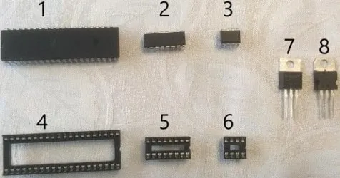
Number | Part | Quantity |
1 | Supported 40-pin MCU | 1 |
2 | 74HC595 | |
3 | DS1307 | |
4 | 40-pin DIP socket | |
5 | 16-pin DIP socket | |
6 | 8-pin DIP socket | |
7 | LM1117 3.3V regulator | |
8 | 7805 5V regulator |
Batteries
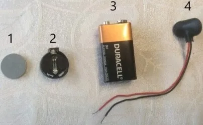
Number | Part | Quantity |
1 | CR2032 coin cell | 1 |
2 | CR2032 coin cell holder | |
3 | 9V battery | 1 (optional) |
4 | 9V battery clip |
Soldering Process
In the images below, all newly soldered/added parts in the step are boxed in yellow.
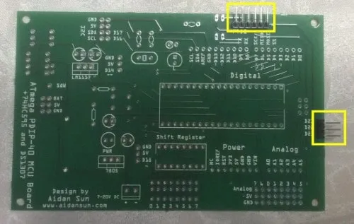 | Solder both right-angle male headers. |
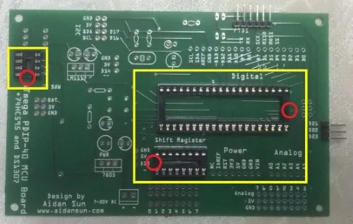 | Solder all IC sockets. Pay attention to their orientation (notches are circled in red). |
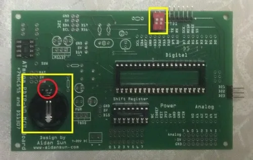 | Solder the DIP switch and coin cell holder. The rectangular bit of the coin cell holder should be pointing up (circled in red). |
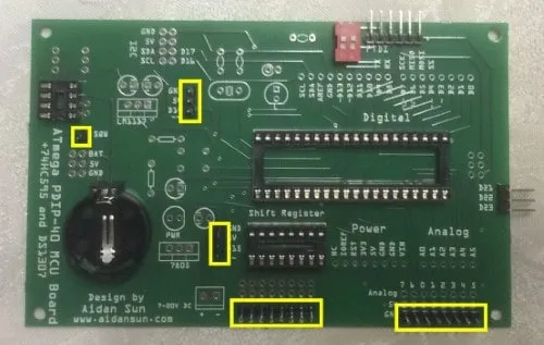 | Solder all single-row male headers. |
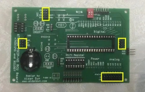 | Solder all double-row male headers. |
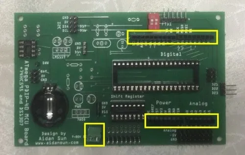 | Solder the female headers and screw terminal. |
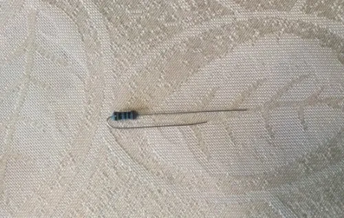 | The shift register’s 220R resistors are mounted vertically to save space. Bend one of the leads so that the leads are parallel. There are nine of these resistors, one is also for the L LED. |
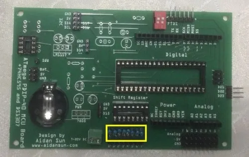 | Solder the shift register’s eight modified 220R resistors. |
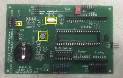 | Solder both crystal oscillators and reset button. |
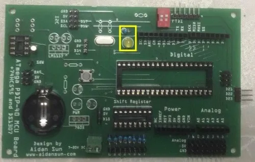 | Solder the yellow L LED and its modified resistor. The anode (longer leg) of the LED should be in the square pad. |
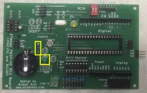 | Solder the green power LED and its normal 220R resistor. The anode (longer leg) of the LED should be in the square pad. |
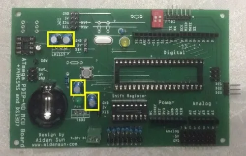 | Solder all electrolytic capacitors. The negative leads of the capacitors should be in the square pads (marked with a small minus sign on both sides). |
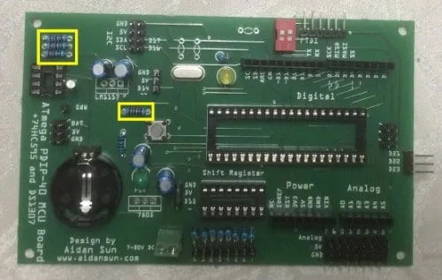 | Solder all 10k resistors. |
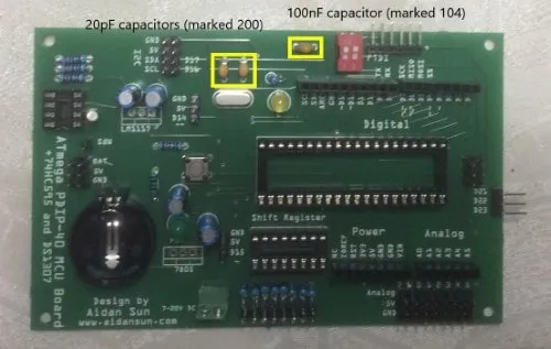 | Solder the ceramic capacitors. Their values are labeled in the image. |
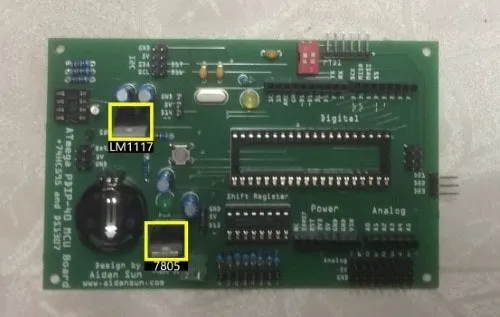 | Solder the voltage regulators. The heatsink should be over the three small rectangles on the PCB. |
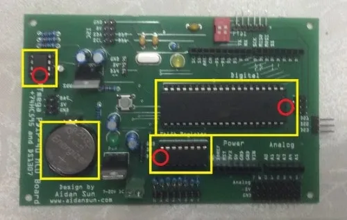 | Insert the ICs into their sockets and the coin cell into its holder. Pay attention to the orientation of the ICs, the notches are circled in red. The coin cell’s + side should be facing up. |
Tip | It is a good idea to mark the box corresponding to the microcontroller you are using. The boxes are on the underside of the PCB, under the ATmega. For example, if you are using an ATmega1284, mark the box next to the word "ATmega1284" with a permanent marker. |
Setting Up
Installing the Arduino Core
Some microcontroller boards (like the ATmega 40 Board) require the installation of an additional software API to work with the Arduino IDE. This is called a core. The ATmega 40 Board uses MightyCore to work with the Arduino environment.
Open the Arduino IDE, then go to .
In the text box marked "Additional Boards Manager URLs", enter this URL:
https://mcudude.github.io/MightyCore/package_MCUdude_MightyCore_index.json. This is the JSON file that will be used to install the core.Exit out of the preferences window by clicking OK, then go to .
Search for "MightyCore" in the search box, then scroll down until you find it. Click Install to install this core. (You may need to wait for the IDE to download the core’s files.)
Once the installation is complete, exit out of the boards manager and go to the board selection menu under . You should see the seven microcontrollers under the MightyCore option.
Burning the Bootloader
The bootloader is a piece of code that sits inside the microcontroller. It runs when you turn on or reset the board. Its main purpose is to receive code from the computer and write it to flash memory. When you buy a new chip, it usually will be blank, with no bootloader. You will then have to flash the bootloader yourself.
To burn the bootloader, you will need:
1x ATmega 40 Board
1x Arduino Uno
6x Male-female jumper wires
Connect the boards together. The table below represents the ATmega 40 Board’s ICSP header with the board viewed from above, coin cell on the left. Pins listed are the Arduino pins to which the corresponding ICSP pin is connected to.
D12
5V
D13
D11
D10
GND
In the Arduino IDE, go to the Tools menu and configure the following:
Board: Arduino Uno
Port: The COM port of your Arduino Uno (will vary)
Programmer: Arduino as ISP
Go to and upload the sketch to your Arduino Uno. This sketch will turn the Arduino into a AVRISP to flash the bootloader.
Once the sketch has been uploaded, select the correct microcontroller for your board under . If the core has been installed successfully, the microcontrollers should appear under "MightyCore".
Click Burn Bootloader under the Tools menu. This will flash the ATmega with the bootloader you selected.
Getting Started
Required Materials
1x ATmega 40 Board
1x 5V FTDI cable
As the ATmega 40 Board contains no onboard USB-to-serial conversion chip, it relies on external circuitry to communicate with your computer. This is provided through an FTDI cable.
Important | FTDI cables can come with different voltage levels, such as 3.3V and 5V. Ensure you are using a 5V-compatible cable. |
Plug the cable’s pin end into the 6-pin FTDI header on the ATmega 40 Board. This is the header next to the DIP switch. When you connect the cable, the black ground wire should be closest to the dot on the PCB:
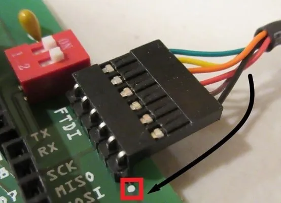
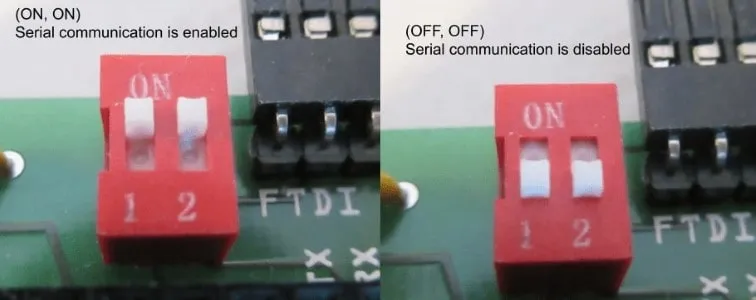
Before uploading programs to the board, make sure that the DIP switch is in the (ON, ON) position. This will enable serial communication over FTDI. If one or both of the channels are in the OFF position, the communication will be disabled and uploading will fail.
Connect the USB end of your cable into your computer. If the power LED does not light, immediately disconnect the cable and check your soldering and connections.
If the power LED does light, you are ready to upload a sketch.
Uploading a Sketch
Note | There should not be a need to install any drivers for the FTDI cable, as the drivers were automatically installed with the Arduino IDE. |
Make sure the correct microcontroller is selected in . You will not be able to upload a sketch to the board without the correct microcontroller selection.
Upload the Blink sketch, shown below, to your board. The "L" LED should start blinking.
/*
   Blink.ino
   Sketch to blink the onboard D13 "L" LED.
   Created on 15 May 2020 by Aidan Sun
*/

void setup() {
  pinMode(13, OUTPUT);
}

void loop() {
  digitalWrite(13, HIGH); // Turn LED on
  delay(1000); // Wait one second
  digitalWrite(13, LOW); // Turn LED off
  delay(1000); // Wait one second
}
PWM on D13 LED
Digital pin 13 is PWM-capable on all microcontrollers. This means that analogWrite can be used to change the brightness of the LED. Upload the sketch below, and the LED should be increasing and decreasing in brightness:
/*
   Fade.ino
   Sketch to fade the onboard D13 "L" LED.

   The "L" LED is connected to D13, which is a PWM pin on all microcontrollers.
   This means that we can change its brightness with PWM.

   Created on 15 May 2020 by Aidan Sun
*/

void setup() {
  pinMode(13, OUTPUT);
}

void loop() {
  for (int i = 0; i < 256; i++) {
    // Step brightness up from 0 to 255
    analogWrite(13, i);
    delay(4);
  }

  for (int i = 255; i > -1; i--) {
    // Step brightness down from 255 to 0
    analogWrite(13, i);
    delay(4);
  }

  // Delay at end of loop to prevent LED from flashing too quickly
  delay(100);
}
Shift Register
The ATmega 40 Board has an on-board 74HC595 shift register. The connections to the microcontroller are below:
Data connects to D18
Latch connects to D19
Clock connects to D20
See 74HC595 Shift Register with Arduino for an example of using a shift register with the Arduino. You can modify the digital pins used in the example to match those listed above.
Note | The ATmega 40 Board contains built-in resistors for the shift register. Therefore, external resistors don’t need to be used when connecting LEDs to the shift register outputs. |
Servos
To test a servo, you will need these parts:
1x ATmega 40 Board
1x 9g standard servo
The ATmega 40 Board has two digital pins next to power pins: D14 and D15. This means that you can directly plug a servo into these pins. In this example, we will be using D15.
Note | The standard Servo library will not work with ATmega 40 microcontrollers since they handle timers differently than the microcontrollers used in typical Arduino boards. |
Fortunately, MightyCore includes an adapted version of the Servo library which does work with these microcontrollers and is accessible with #include <Servo.h>. This means that from the code, there will be no difference from controlling a servo using the built-in Servo library.
When you upload and run the code below, the servo should start moving back and forth:
/*
   Sweep.ino
   Sketch to control a servo.
   Created on 18 May 2020 by Aidan Sun

   Circuit: One standard 9g servo connected to D15 of the ATmega 40 Board
*/

#include <Servo.h> // Include the servo library for ATmega 40

Servo s;  // Create a servo object

void setup() {
  s.attach(15);  // Servo is connected to D15
}

void loop() {
  for (int i = 0; i < 181; i++) {
    // Increment angle from 0 to 180
    s.write(i);
    delay(10);
  }

  for (int i = 180; i > -1; i--) {
    // Decrement angle from 180 to 0
    s.write(i);
    delay(10);
  }
}
On-board RTC
Important | The RTC cannot be used with the ATmega8535. This is due to the small memory size of the microcontroller. |
The ATmega 40 Board contains an on-board DS1307 RTC. This RTC uses I2C to communicate. Using the on-board RTC will be exactly the same as using an external one with Arduino.
I have written a separate tutorial on using a DS1307 with Arduino.
Note | The RTC requires my DS130X library. Download the library in Zip format | DS130X Documentation |
Once you have read the tutorial and installed this library, go to .
After uploading and running the code, open the serial monitor. There should be a steady stream of timestamps read from the RTC:
Fri, 28/08/20 10:05:50
Fri, 28/08/20 10:05:51
Fri, 28/08/20 10:05:52
Fri, 28/08/20 10:05:53
Fri, 28/08/20 10:05:54
Fri, 28/08/20 10:05:55
Fri, 28/08/20 10:05:56
Fri, 28/08/20 10:05:57
Fri, 28/08/20 10:05:58
Fri, 28/08/20 10:05:59
Reading Coin Cell Voltage
The ATmega 40 Board has a 2⨯3 header containing only power pins. This header is located to the left of the coin cell.
The top row (labeled BAT) is connected to the coin cell’s output. This means that you can use the pins to read the voltage of the coin cell without having to take it out.
Tip | Both pins in the BAT row are connected. This means that you can use either pin to read the coin cell. |
To read the coin cell with the ATmega 40 Board, connect one of the BAT pins to analog input A0. The code below reads the analog value on A0, then converts it into a voltage to determine the state of the coin cell.
/*
   TestCoinCell.ino
   Sketch to print the voltage of the coin cell to the serial monitor.
   Baud rate: 9600 baud

   Circuit: Connect one of the "BAT" pins to A0.

   Created on 15 May 2020 by Aidan Sun
*/

void setup() {
  Serial.begin(9600); // Open a serial port
  Serial.print("Coin Cell Test - ");

  // Get A0 readings
  int analogIn = analogRead(A0);

  // Get voltage from analog reading
  // The maximum voltage that can be read is 5V and the number of possible values returned
  // by analogRead() is 1024.
  // Divide 5 by 1024 to get a scale factor of 0.0048. Multiply this scale factor by the
  // analog reading to get voltage.
  float voltage = analogIn * 0.0048;

  // Print the voltage to one decimal
  Serial.print(voltage, 1);
  Serial.print("V "); // Print the unit (volts)

  if (voltage >= 2.0) {
    // If the battery is 2.0V or above, it is OK.
    Serial.println("Battery OK");
  }
  else {
    // If the battery is less than 2.0V, it needs to be replaced.
    Serial.println("Replace battery.");
  }
}

void loop() {} // No loop
After uploading and running the sketch, open the serial monitor. It will display the voltage read from the coin cell. If the coin cell has a voltage above 2V, it will print 'OK'. Otherwise, it will tell you to replace it. This is a sample output:
Coin Cell Test - 3.2V Battery OK
Issues with Arduino Compatibility
Below are some limitations of the compatibility of the ATmega 40 Board with the Arduino environment, including software and hardware issues.
Software Issues
No support for Pin Change Interrupts (PCINTs). This means that libraries that use PCINTs are not compatible on these microcontrollers (example. SoftwareSerial).
The standard Servo library will not work with these microcontrollers. (Note that this problem is solved through MightyCore, which provides an adapted library with the same
#include <Servo.h>.)When porting code from a different board, the memory size of the microcontroller may be different. If the ATmega 40 microcontroller has less memory than the original board, porting and uploading may fail. See the Technical Details above for a comparison of memory sizes for these microcontrollers.
Hardware Issues
The I2C pins on ATmega 40 microcontrollers are different than on the standard Arduino Uno. This means that any shields that use I2C are not compatible on the ATmega 40 Board.
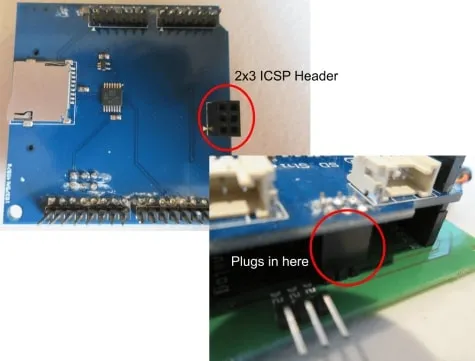
The SPI pins on ATmega 40 microcontrollers are different than on the standard Arduino Uno. This means that any shields that use SPI must communicate via the ICSP header, which is standard across all Arduino boards.
An easy way to tell if a shield uses ICSP is by looking at its underside - if it has a black 2⨯3 header on the back and it plugs into the ICSP header, the shield uses ICSP and is compatible.
Serial Communication Issue
On ATmega 40 microcontrollers, TX and RX are now on digital pins 9 and 8, respectively. This means that using these pins for general I/O use could disrupt serial communications, but on a standard Arduino, this will pose no issue.
The workaround for this issue is the DIP switch on the board: when set to (ON, ON), digital pins 8 and 9 will have a connection to the FTDI header. This allows serial communication to occur, but these pins cannot be used for general I/O.
When set to (OFF, OFF), the pins will no longer be connected to the FTDI header. This will essentially turn the FTDI cable into a 'power-only' type cable - the device receives power, but the data lines for communication are not connected. This will free up pins 8 and 9 so you can use them for I/O.
Important | If the DIP switch is in the (OFF, OFF) position, uploading sketches and serial communication will fail. |
